Power disc brakes really improve safety. I wanted to install a power brake booster and MC without having to delete my factory air cleaner. Keeping my 1963 C10 looking as close to factory as possible under the hood was my goal. Information here will help with V8 applications too.
This DIY shows the installation of a power brake booster and dual master cylinder in a 1963 Chevy C10 with a factory 230ci engine and air cleaner. Depending on your application, the steps outlined here may not work for you.
THE PROBLEM
I installed a 1995 Chevy Blazer brake booster and MC in my 1965 C10. It works great but I was forced to use an aftermarket 9" air cleaner because the booster doesn't allow enough room for the factory air cleaner.
I installed a 1995 Chevy Blazer brake booster and MC in my 1965 C10. It works great but I was forced to use an aftermarket 9" air cleaner because the booster doesn't allow enough room for the factory air cleaner.
THE SOLUTION
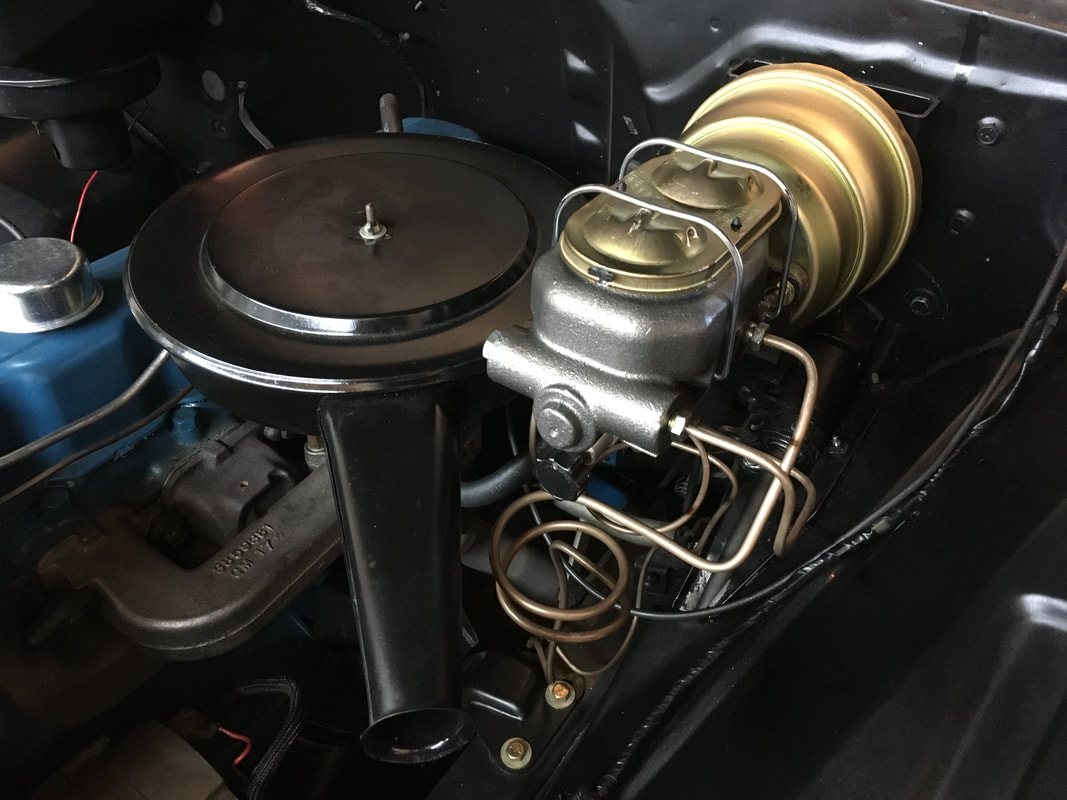
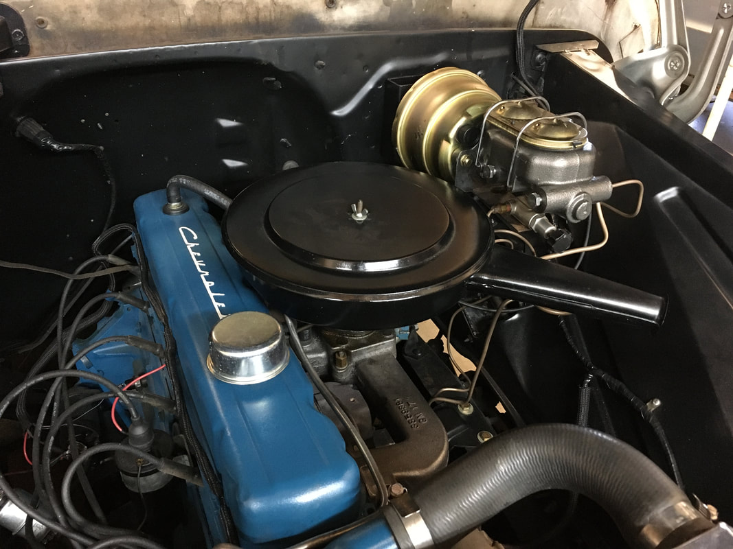
A 7" power brake booster and dual MC allows me to keep my 1963 C10 air cleaner and a factory appearance under the hood.
A 7" power brake booster and dual MC allows me to keep my 1963 C10 air cleaner and a factory appearance under the hood.
THE DETAILS
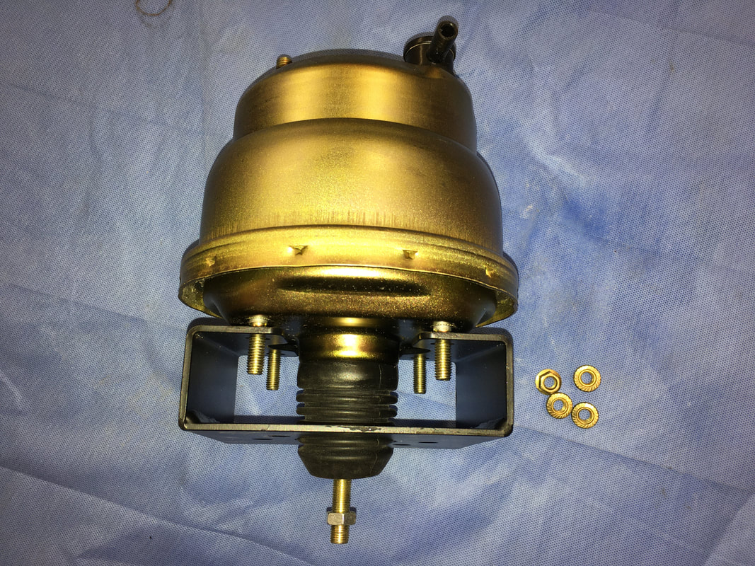
I purchased a 7" power brake booster and disc/drum brake MC from a vendor on eBay. The kit was $96 USD delivered to my door. The widest part of the booster is only 7". The MC has a 1" bore and is for disc/drum. The MC has 4 ports so the brake lines can connect to either side of the MC.
I purchased a 7" power brake booster and disc/drum brake MC from a vendor on eBay. The kit was $96 USD delivered to my door. The widest part of the booster is only 7". The MC has a 1" bore and is for disc/drum. The MC has 4 ports so the brake lines can connect to either side of the MC.
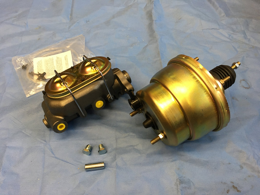
I also purchased a firewall adapter bracket from CaptainFab. These brackets are well made. Four grade 8 bolts are included. You can email him at [email protected] for more info about his products. I ordered a bare steel firewall bracket and painted it satin black so it would match my engine bay paint.
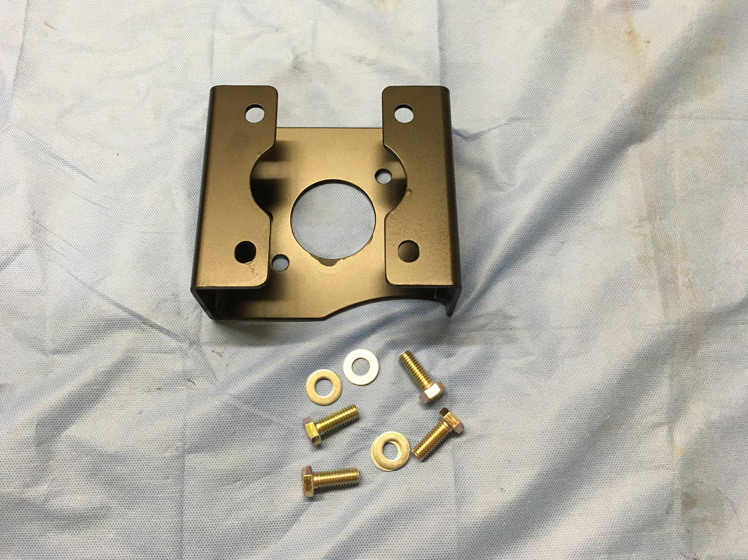
The firewall bracket fits the booster perfectly.
My C10 already has front disc brakes and a dual pot MC, but no booster. I'll replace this MC with the new one in the kit.
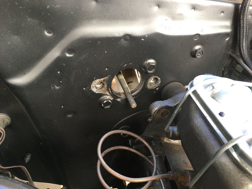
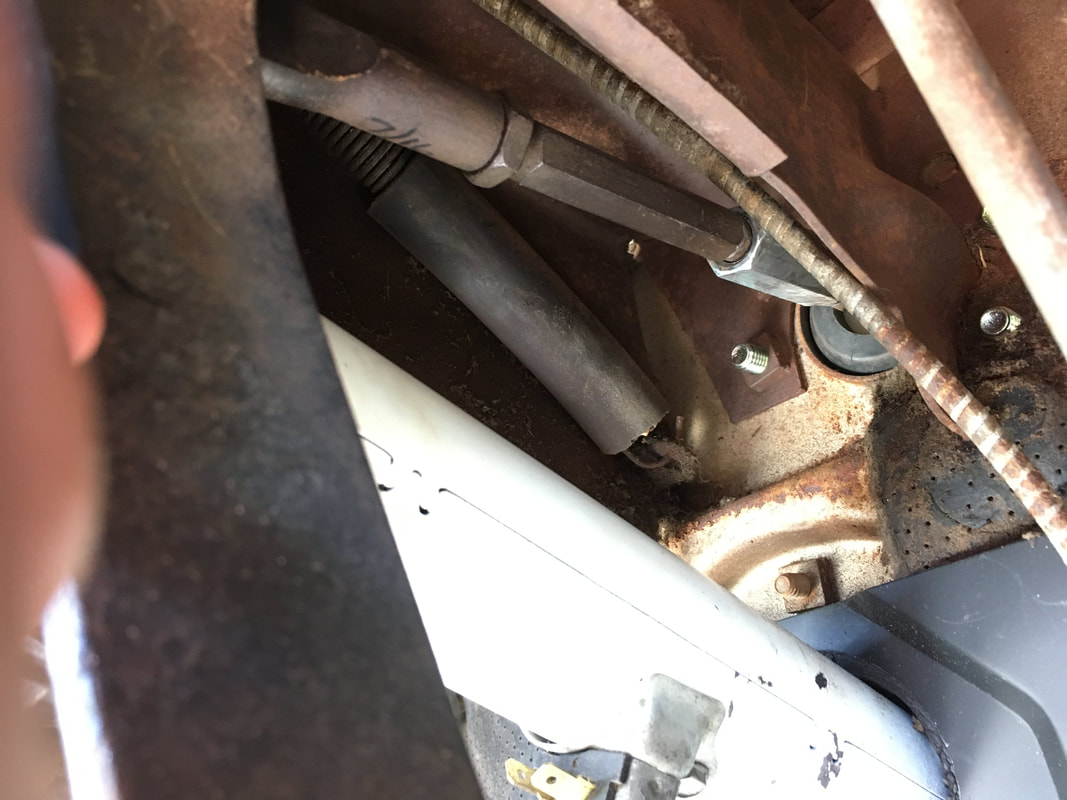
The two bolts that held the MC to the firewall have been removed. All 4 bolts will be removed from the firewall. You can see the brake pedal push rod sticking through the firewall. Go inside the cab and remove the pedal push rod from the brake pedal arm using a 3/4" and 9/16" wrenches.
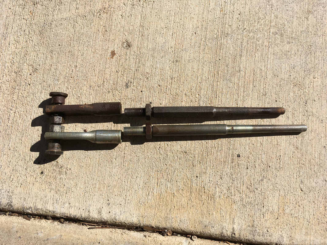
Not all brake push rods are the same length.
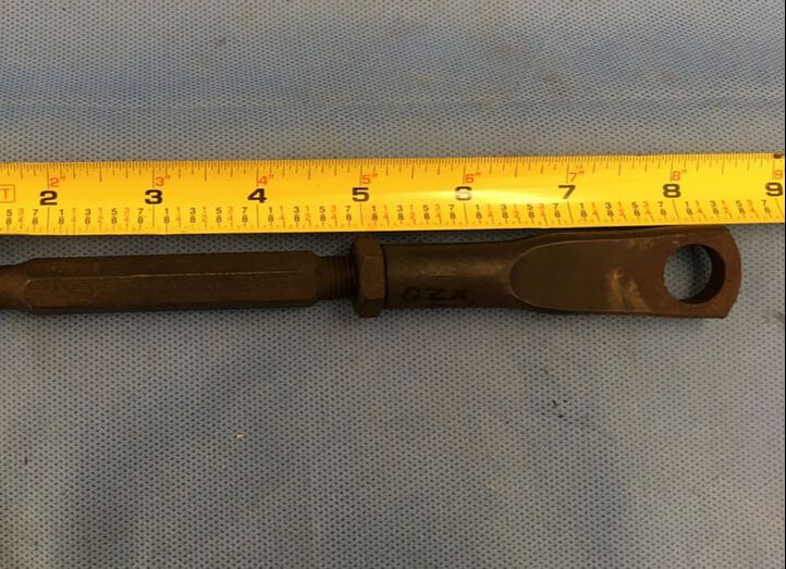
When I converted my 1963 C10 to a disc/drum MC WITHOUT a booster, I needed to use a longer push rod (bottom). My 1963 push rod was too short (top).
When I converted my 1963 C10 to a disc/drum MC WITHOUT a booster, I needed to use a longer push rod (bottom). My 1963 push rod was too short (top).
Using the 4 bolts and washers supplied in the CaptainFab kit, bolt the firewall bracket in place.
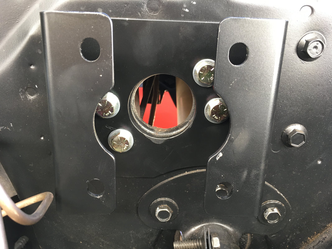
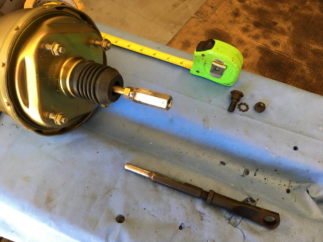
Use 2 nuts to secure the booster for a test fit. You will remove the booster after making some measurements.
Inside the cab, measure the distance from the end of the booster push rod to the center of the hole in the brake pedal arm. I measured 8" but yours might be different.
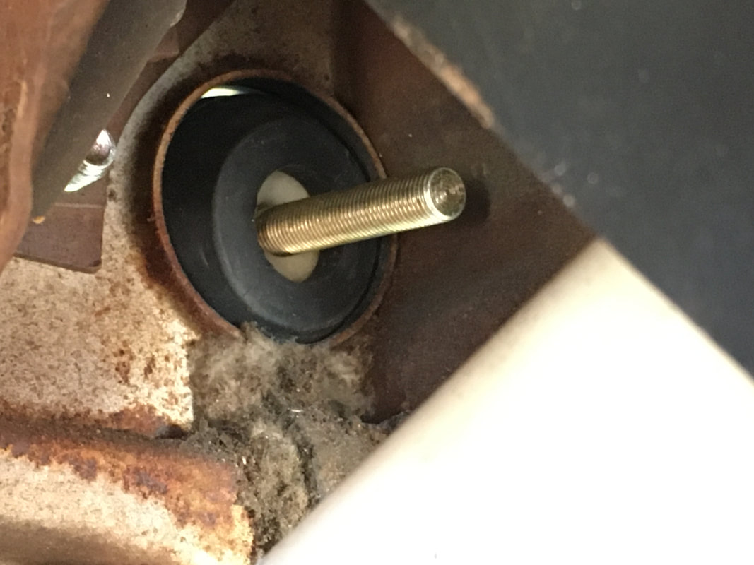
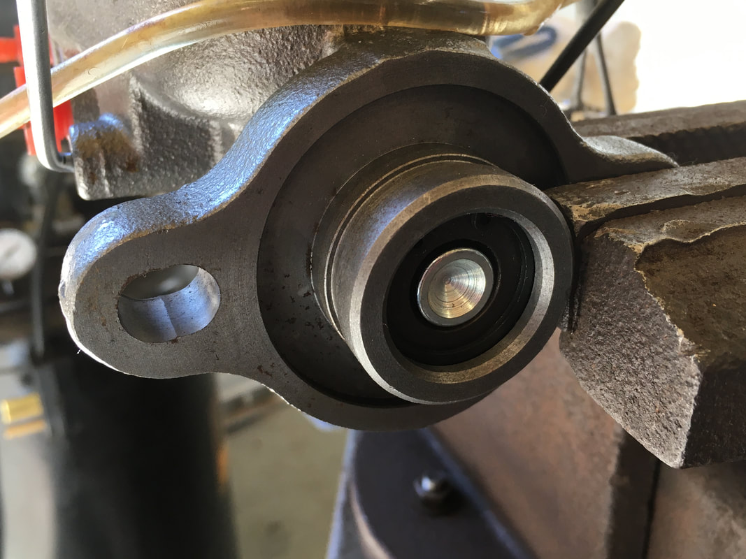
The photo below shows how the end of a brake pedal push rod fits inside the MC piston when the MC is mounted directly to the firewall. With a booster, there is no place to insert the pedal push rod.
To solve this, we'll fabricate a cup to put on the end of the booster rod to provide a place to insert the pedal push rod.
To solve this, we'll fabricate a cup to put on the end of the booster rod to provide a place to insert the pedal push rod.
It's very easy to fabricate a simple but strong cup on the end of the booster push rod.
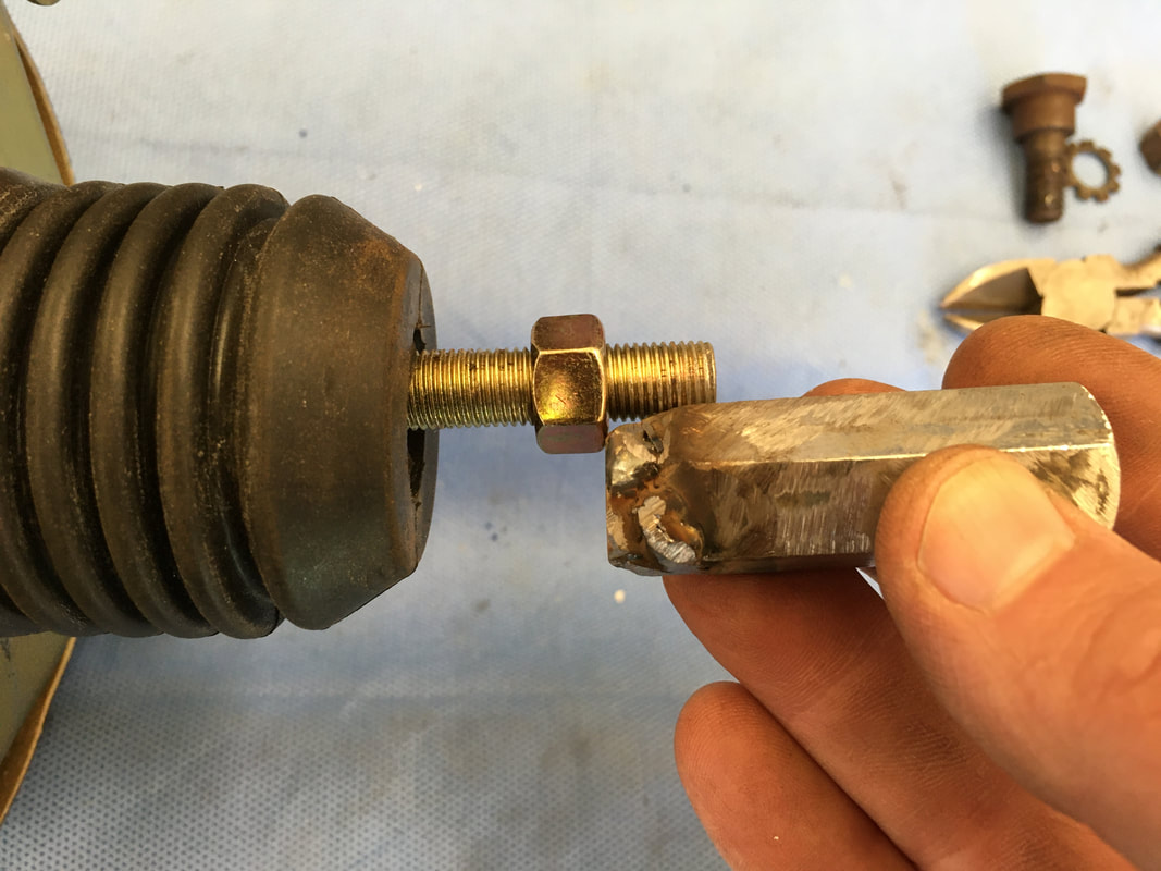
I bought a 1 + 3/4" long steel coupling nut with 1/2" - 13 threads. The inside diameter is perfect for the pedal push rod. The pedal push rod fits right inside but is not too tight or too loose. The pedal push rod can slide in and back out without binding.
Here's the plan:
The threads of the booster rod are 3/8" - 24 fine thread. So I'll weld a 3/8" - 24 fine thread nut on the end of the coupling nut so I can screw it onto the end of the booster rod.
Let's call this fabricated piece a Booster Rod Cup.
The threads of the booster rod are 3/8" - 24 fine thread. So I'll weld a 3/8" - 24 fine thread nut on the end of the coupling nut so I can screw it onto the end of the booster rod.
Let's call this fabricated piece a Booster Rod Cup.
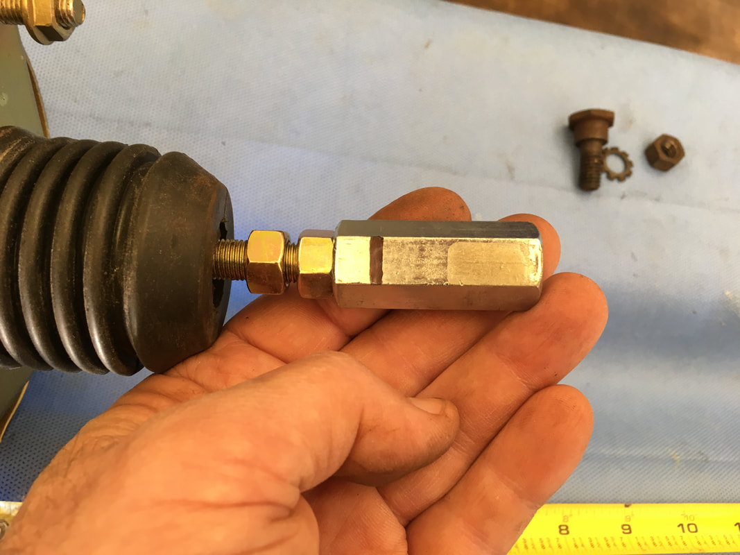
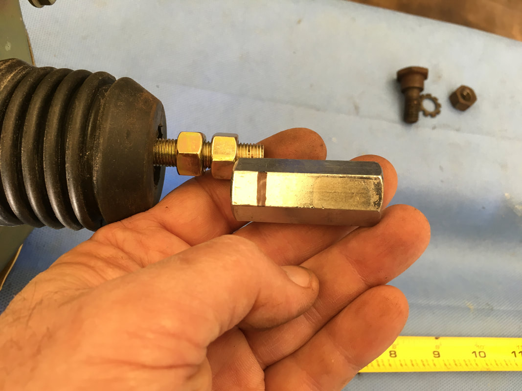
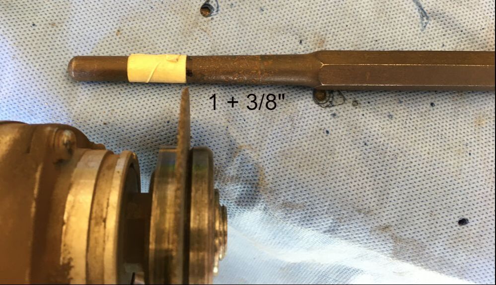
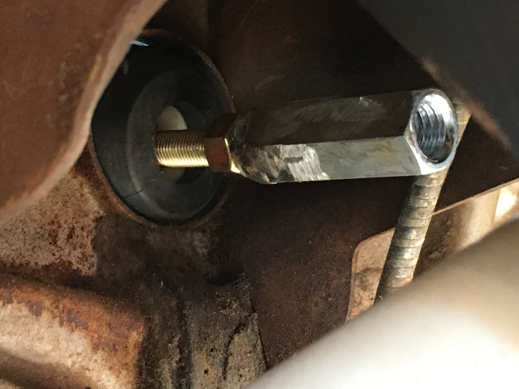
Once fabricated, the Booster Rod Cup will thread onto the rod until the rod reaches the black line. That way there will be at least 1 + 3/8" of empty space inside the coupling nut (to the right of the black line) to receive the end of the pedal push rod. These two pictures show the plan BEFORE the nut was welded to the coupling nut.
|
|
A 3/8" - 24 bolt is threaded inside the nut to help steady it while welding.
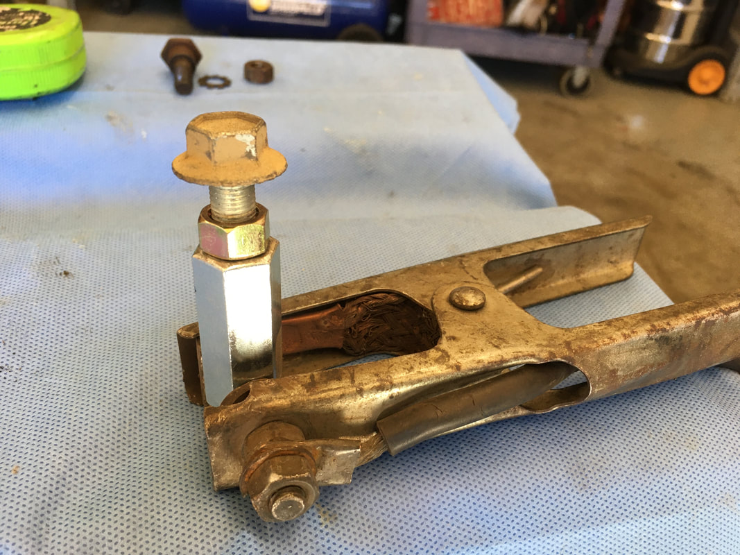
My weld needs a little cleaning up, but you get the idea. Next, screw the Booster Rod Cup onto the booster rod until it meets the jamb nut. Adjust the Booster Rod Cup so there's at least 1 + 3/8" of empty space inside.
Tighten the jamb nut against the Booster Rod Cup to lock it in place.
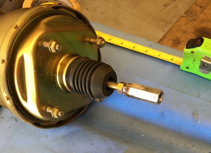
Adjust the threads of the pedal push rod so it's at the half way point. That way you can adjust it both ways when the time comes.
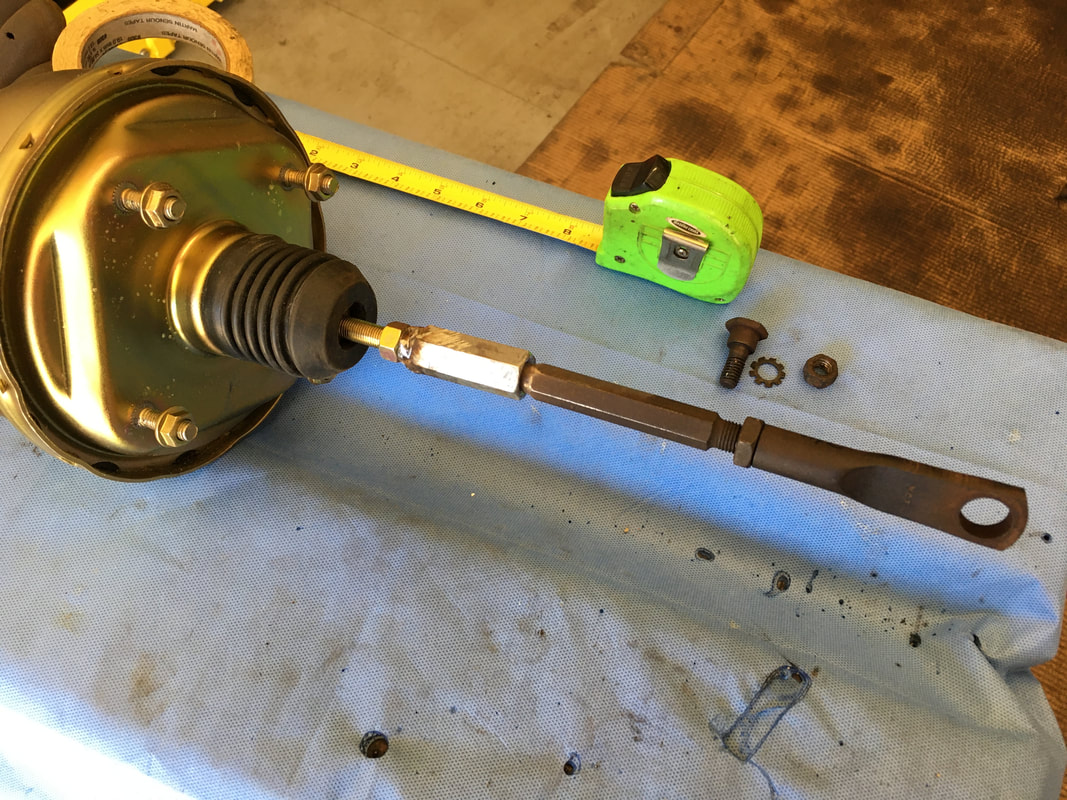
In my application, I need 8" from the end of the booster push rod to the center of the pedal arm hole. Since the end of the pedal push rod will touch the end of the booster rod (inside the Booster Rod Cup), I measured and marked the pedal push rod at 8" (center of the bolt hole to the tape mark). Before I made the cut, I made sure there was at least 1 + 3/8" of pedal push rod (the skinny part) that would fit inside the Booster Rod Cup. I want the pedal push rod to contact the end of the booster push rod.
After cutting the pedal push rod, test fit to make sure it fits nicely inside the Booster Rod Cup. Notice the pedal push rod adjustment threads are about half way.
|
|
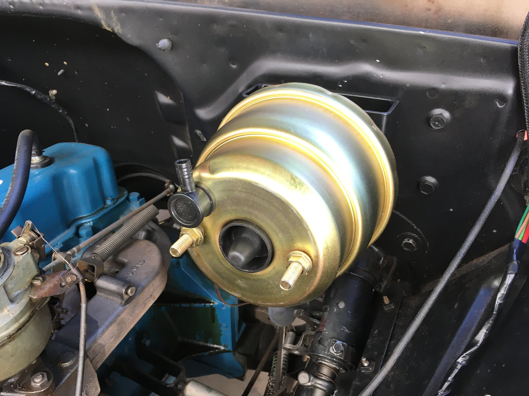
Bolt the booster back onto the firewall bracket.
A look inside the cab.
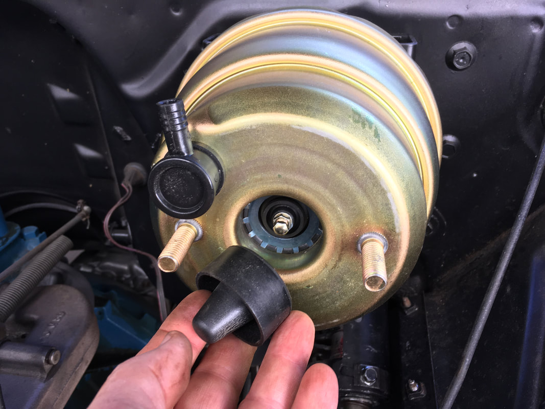
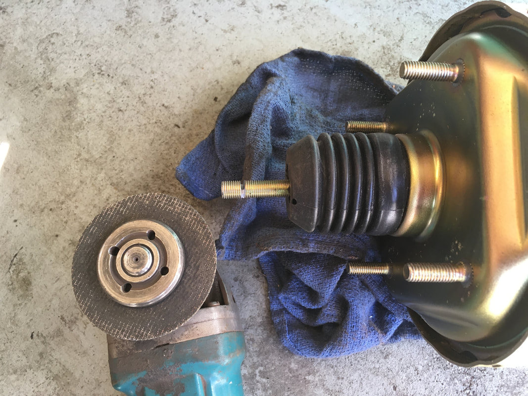
Remove the rubber boot that protects the intermediate push rod.
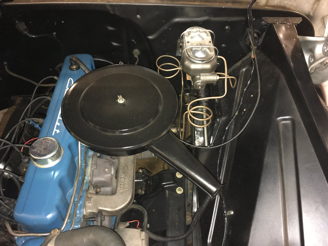
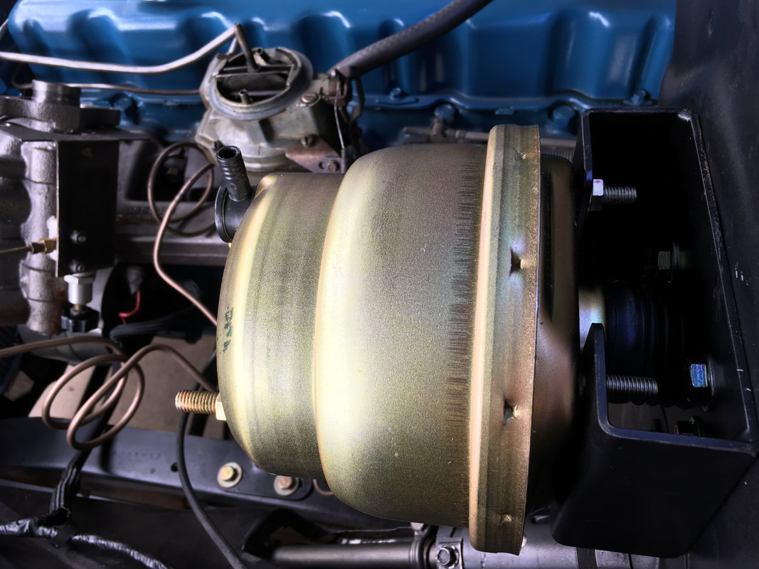
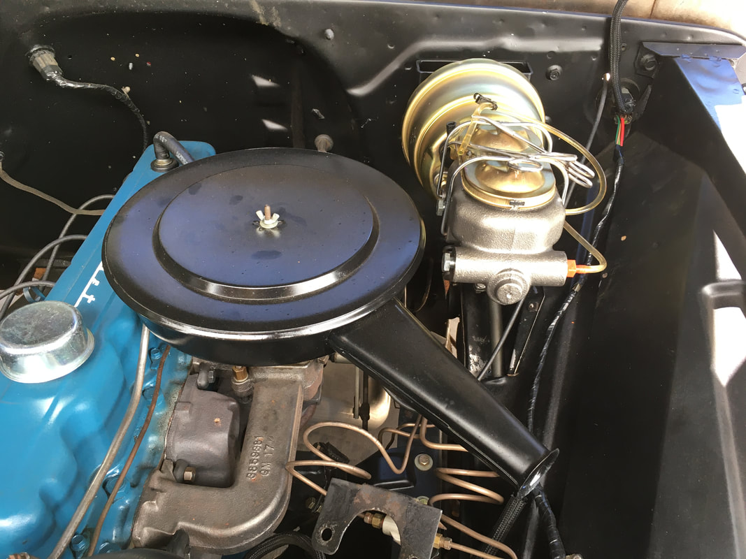
Test fit the master cylinder and air cleaner. Everything seems to fit.
Remove and then bench bleed the MC to remove the air.
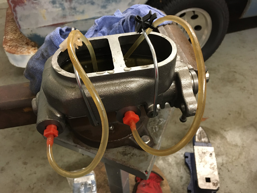
Remember to put the steel rod inside the MC before you reinstall it on the booster.
Put the end of the Pedal Push Rod inside the Booster Rod Cup and then bolt the Pedal Push Rod to the pedal arm. Adjust the threads of the pedal push rod so there is only a little free play in the pedal. About 1/4" - 3/8" of free pedal movement is about right. Lock the Pedal Push Rod jamb nut once the adjustment is made. Press the brake pedal with your hand and watch the Pedal Push Rod move. It should have a little free play but should NOT piston back and forth very much inside the Booster Rod Cup.
I needed to cut the booster rod a little shorter to make things fit better. If you also need to make an adjustment, it's better to remove the Booster Rod Cup, cut the booster rod shorter, and then put the Booster Rod Cup back on. You always want at least 1 + 3/8" of the Pedal Push Rod to fit inside the Booster Rod Cup.
Everything fits well after my adjustment.
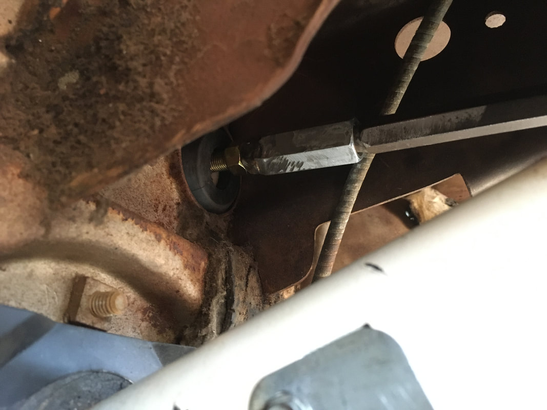
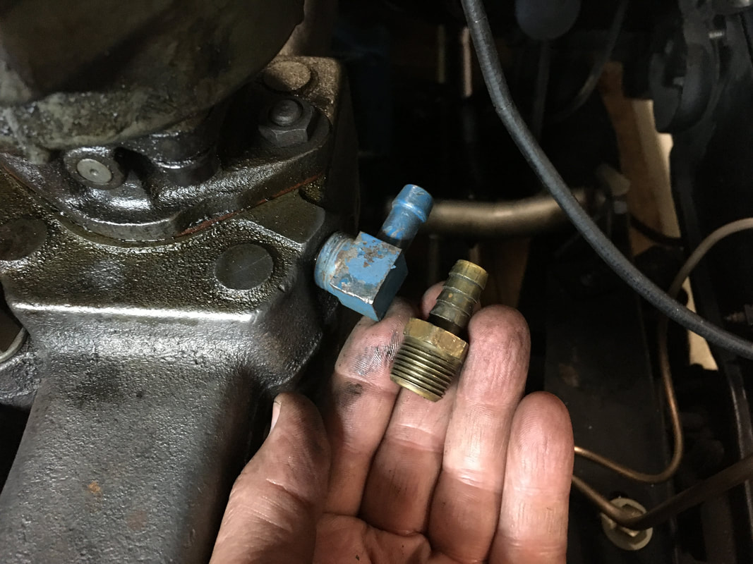
There is a solid plug in the intake manifold just below the carburetor. Replace the plug with a straight or right angle barbed brass fitting. The threaded end will be 3/8" Male Iron Pipe (M.I.P.) The size of the barbed end will depend on the booster vacuum hose inside diameter.
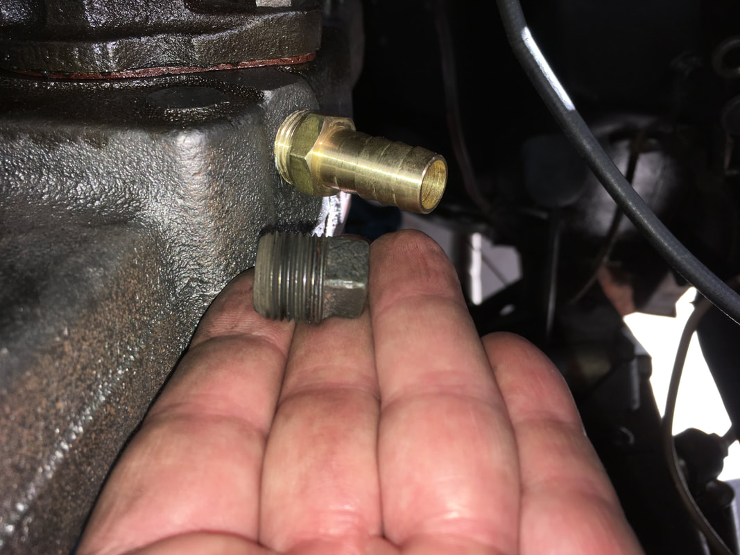
My booster valve was 3/8" so I used a 3/8" right angle barbed fitting. A straight fitting was also an option.
I used roughly 2 feet of vacuum tubing with a 3/8" inside diameter. Starting at the booster valve, my vacuum tubing goes between the booster and the MC towards the DS fender and then under the booster to the manifold port.
It's time to connect the hard lines, bleed the brakes and take it for a test drive.
It's time to connect the hard lines, bleed the brakes and take it for a test drive.