1963 Chevy C10 Steering Column Installation
Your rebuilt steering column can be installed without a struggle if you follow these steps. Before you begin, make sure your steering gear box is in good shape and ready for service.
Working through the DS front wheel well, position the steering shaft part way through the opening in the firewall. Do not put the steering shaft coupler (rag joint) onto the steering gear box shaft just yet. Make sure you have the lower shaft clamp and spring on the shaft.
Make sure you have the lower support spring and clamp loosely positioned on the shaft before going on to the next step.
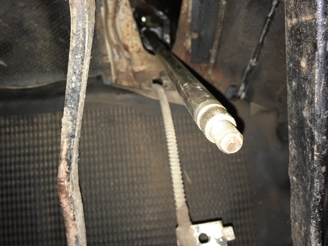
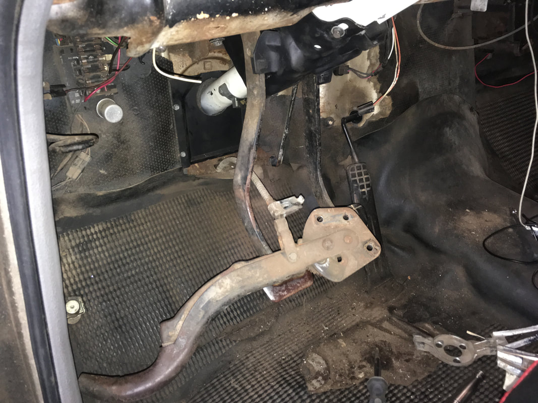
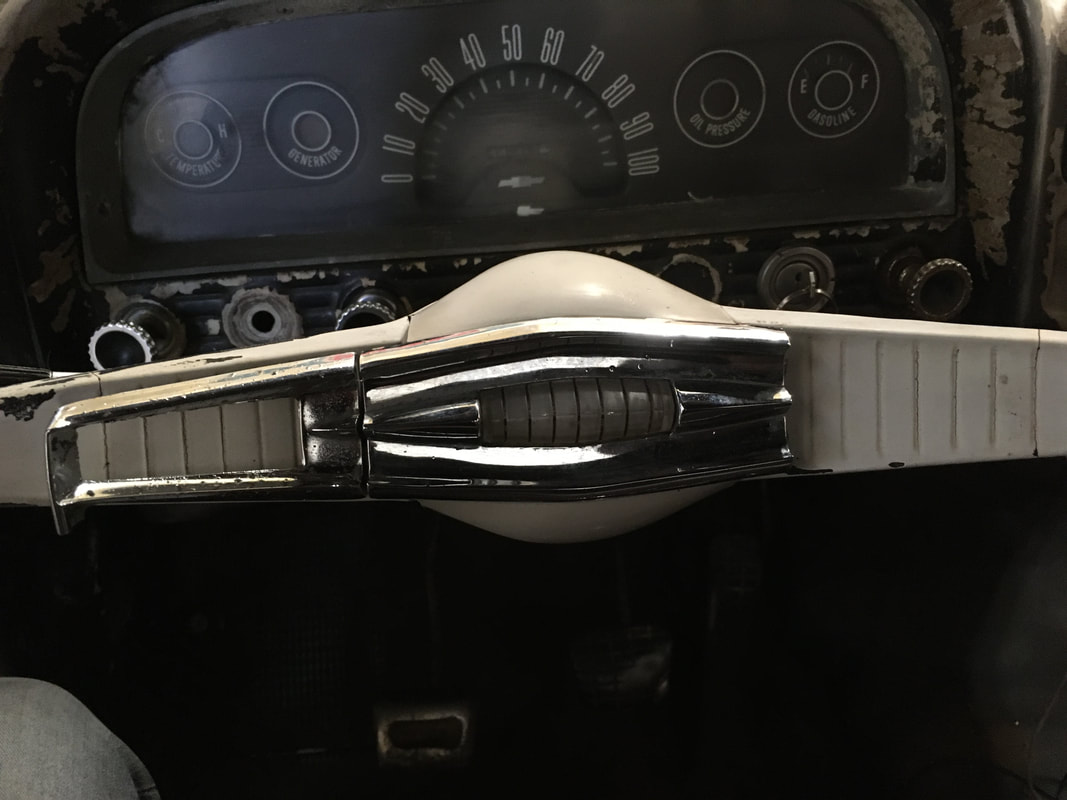
Position the shaft between the pedal arms. The line marked on the very end of the shaft should be positioned at 12 o'clock and the front wheels pointing straight ahead.
|
|
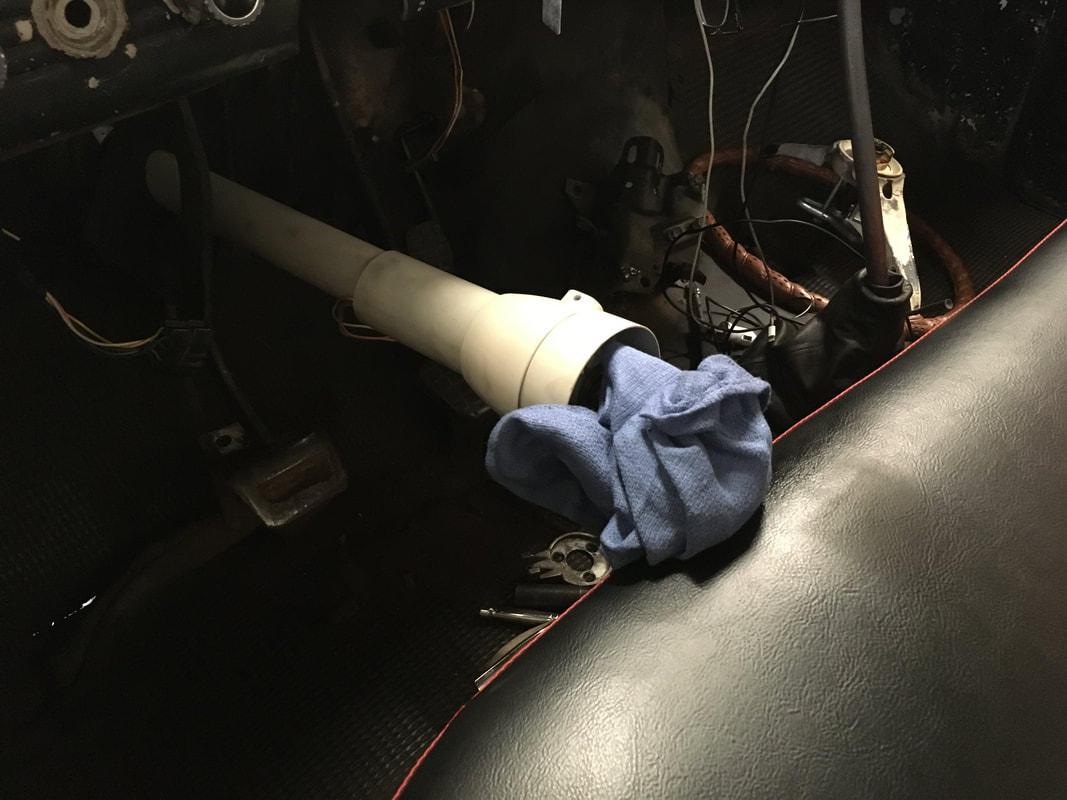
Slide the column onto the shaft until the shifter arms on the lower end are through the firewall.
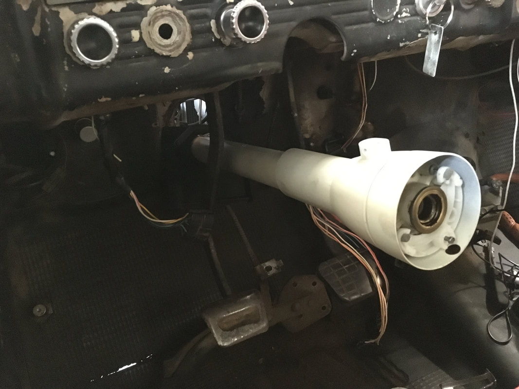
Next, slide the steering shaft up through the column and past the upper bearing. Secure a shop rag on the end of the shaft so it doesn't accidentally damage the seat during the next few steps.
|
|
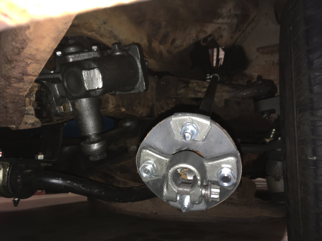
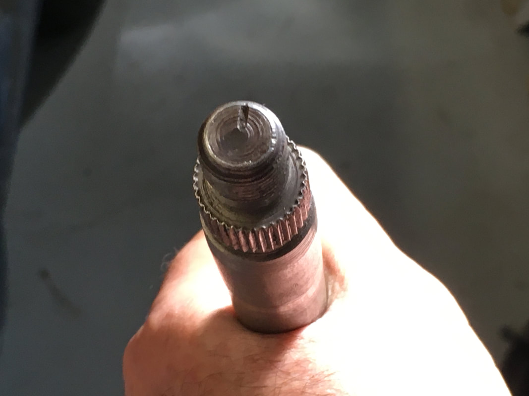
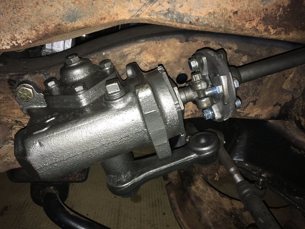
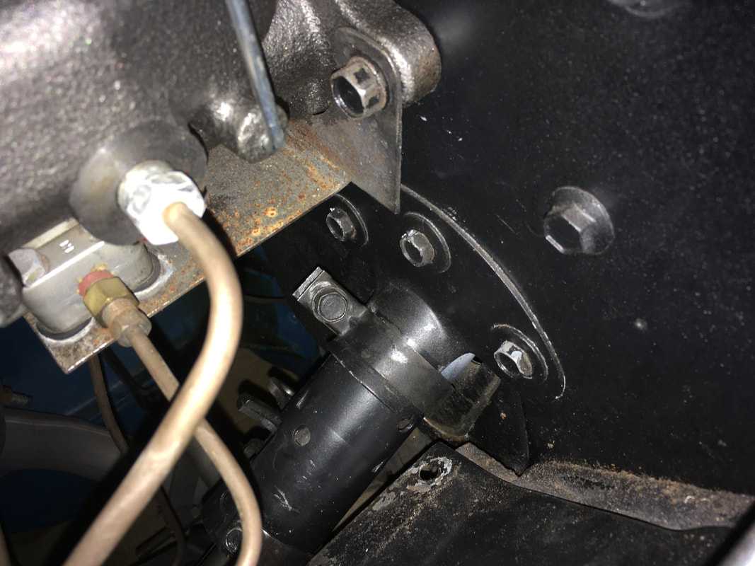
With the front wheels pointing straight ahead, the steering box shaft should be in the centered position. Make sure the mark on the steering wheel end of the shaft is at 12 o'clock. Next, tap the coupler onto the steering box shaft.
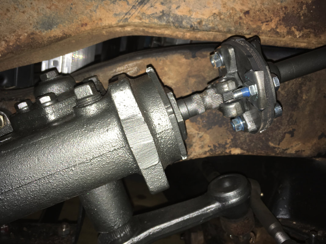
The steering box shaft has a recessed area between the two sections with splines. Line the recessed area up with the coupler bolt.
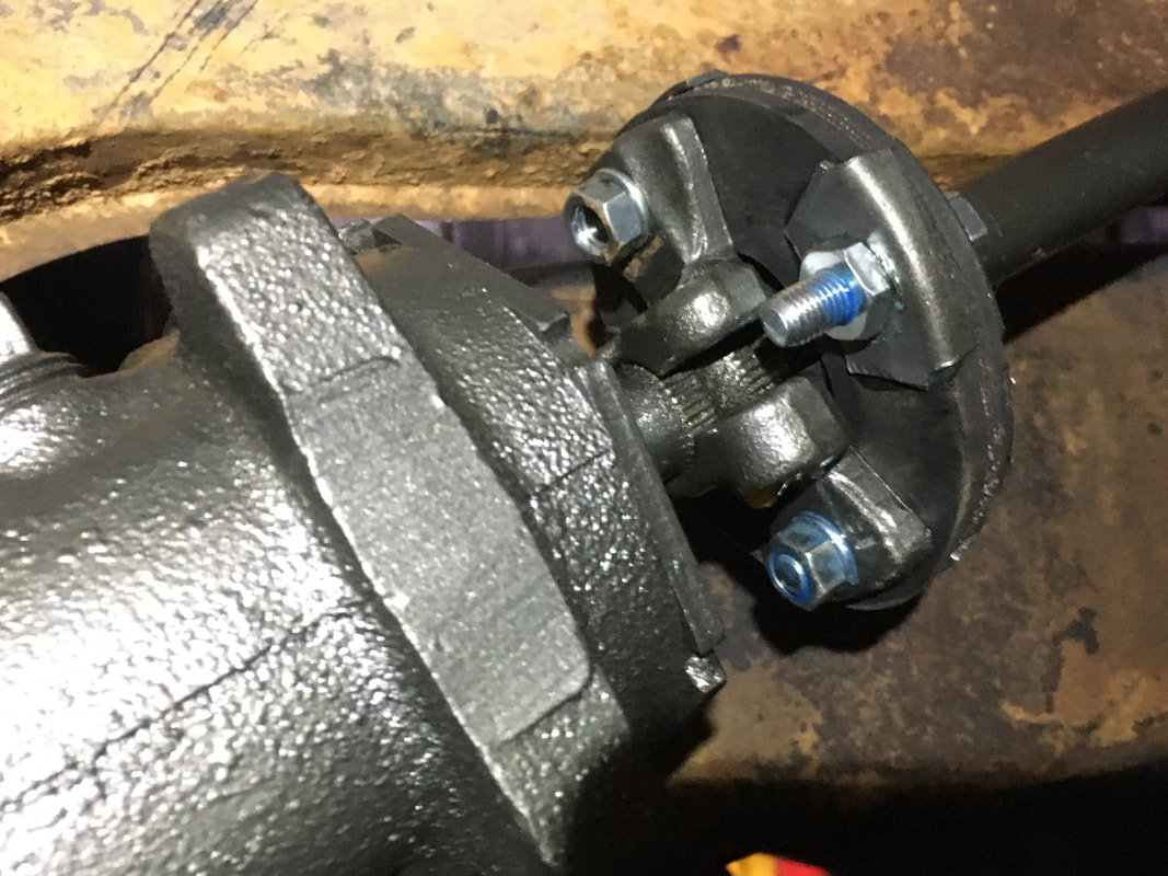
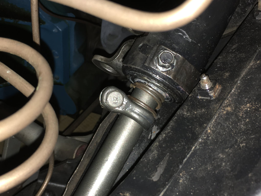
You can now connect the couplers.
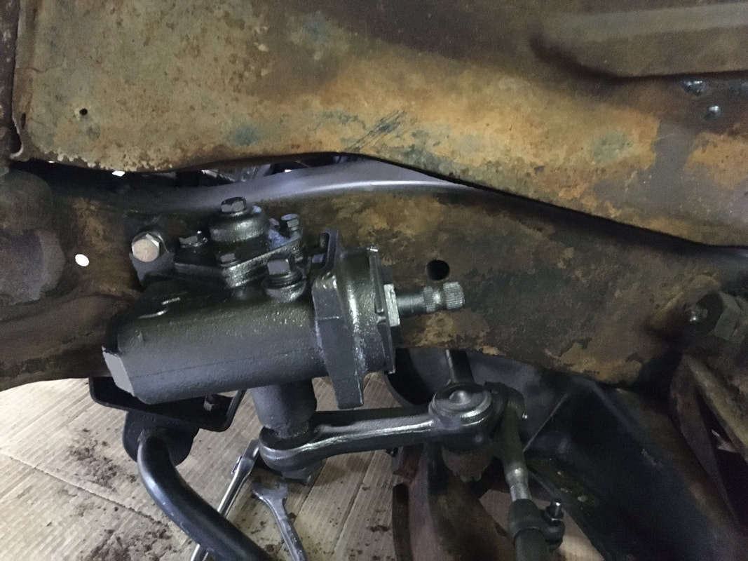
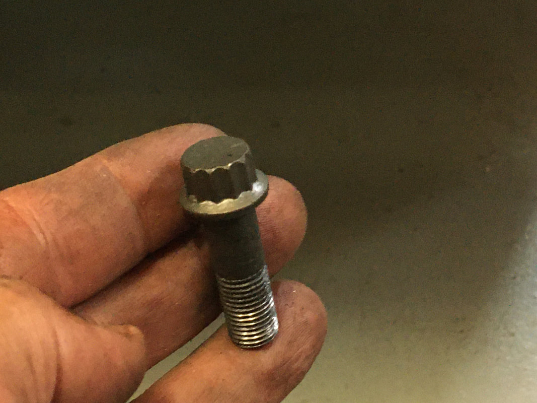
A 7/16" 12 point socket is needed to tighten the bolt to the coupler. Use medium thread-lock, The coupler bolt tightens the splines on the steering box shaft and also acts as an interference bolt so the coupler won't pull off the shaft.
|
|
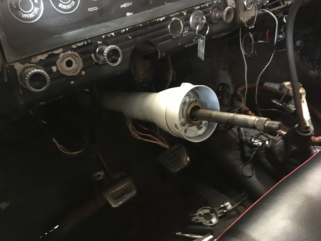
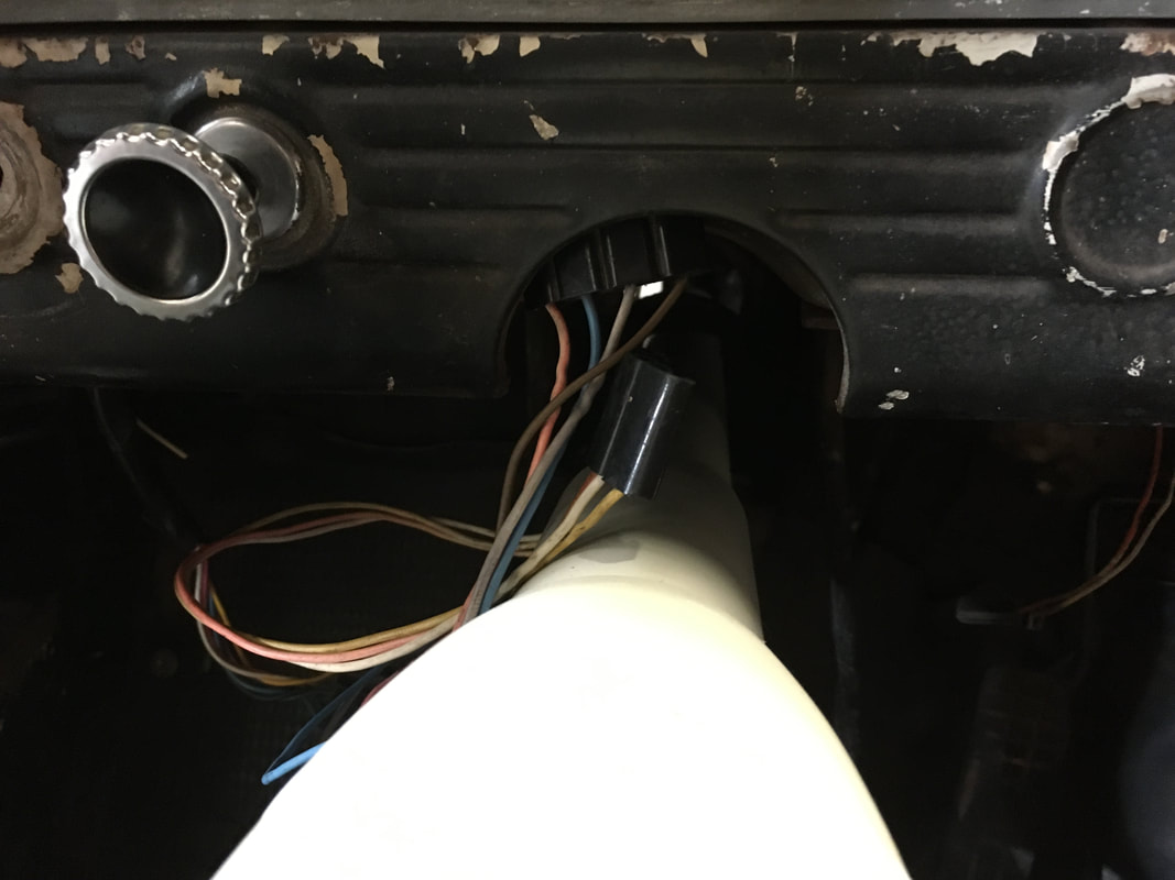
Orient the column so the wires are on the left. The opening for the turn signal lever should also be on the left. Feed the plastic wire couplers up into the dash and to the left.
|
|
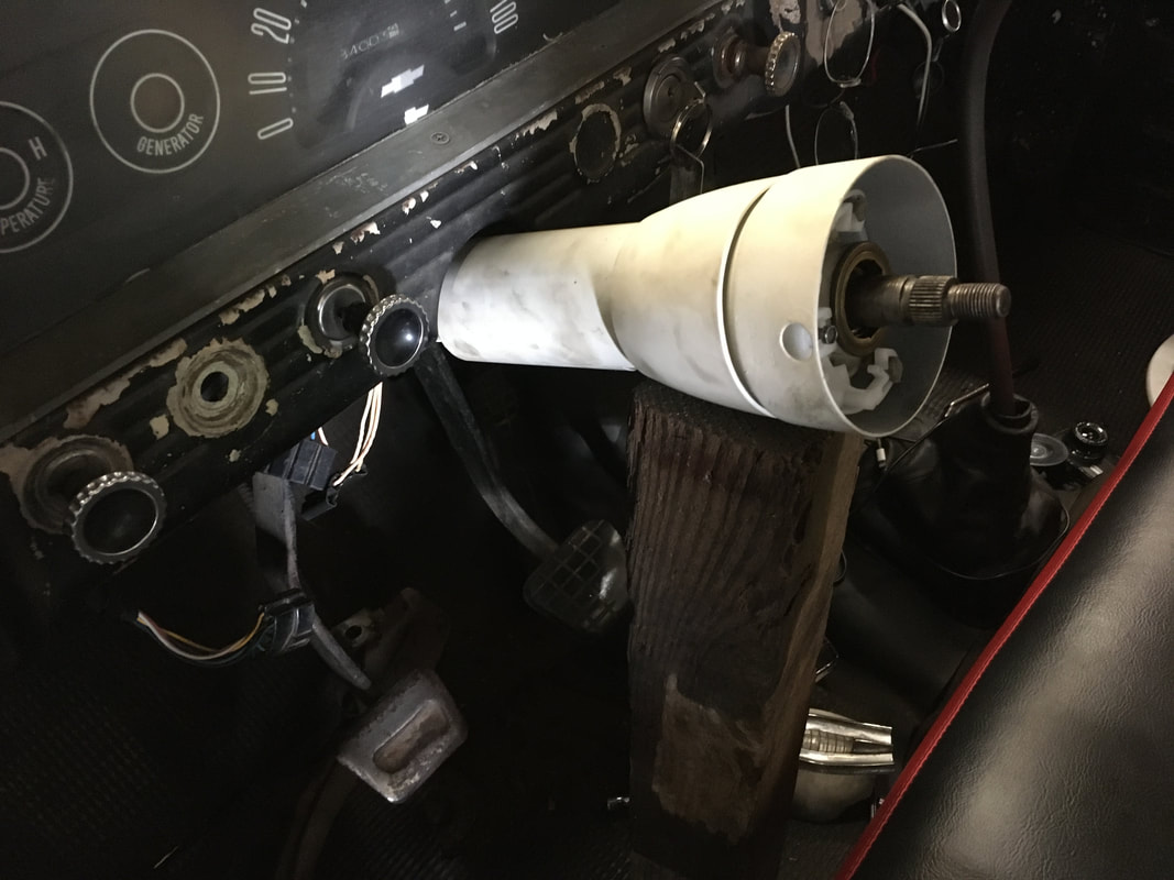
Use a block of wood to support the steering column so it's easier to install the coulmn support bracket.
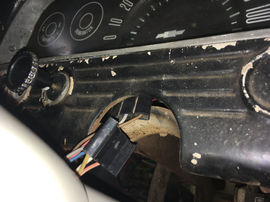
Connect the wire couplers.
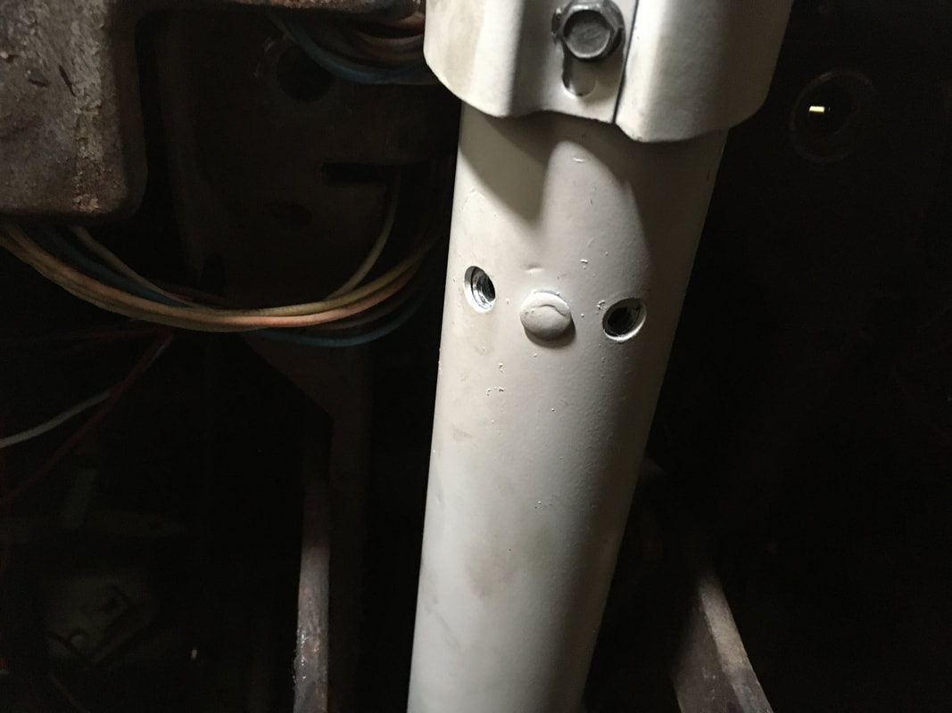
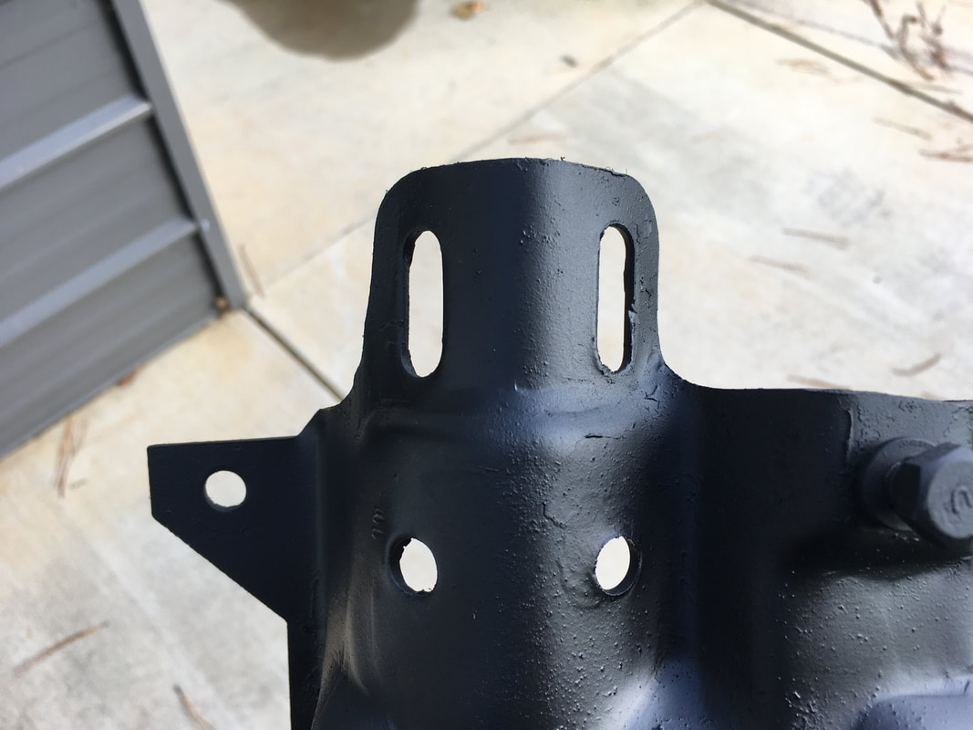
The 2 bolt holes on the underside of the column correspond to the slotted holes on the support bracket.
|
|
Bolt the column support bracket into place. Loosely connect the 2 bolts through the slots and to the column. Make them only finger tight for now.
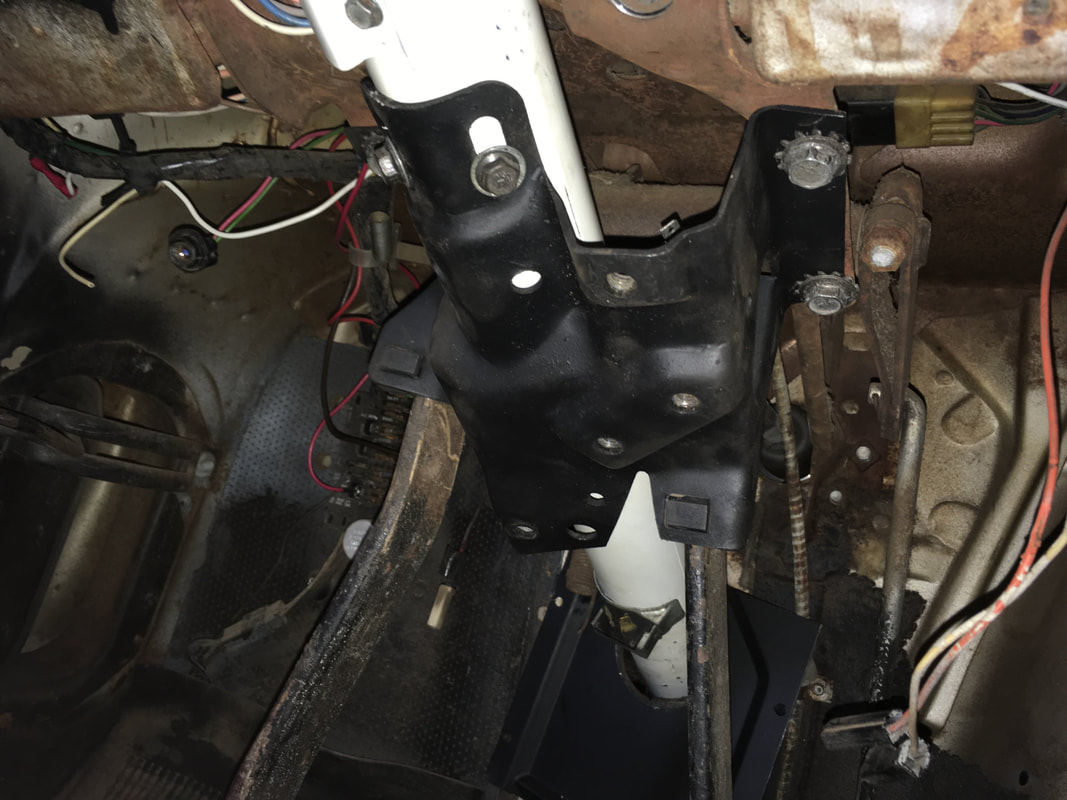
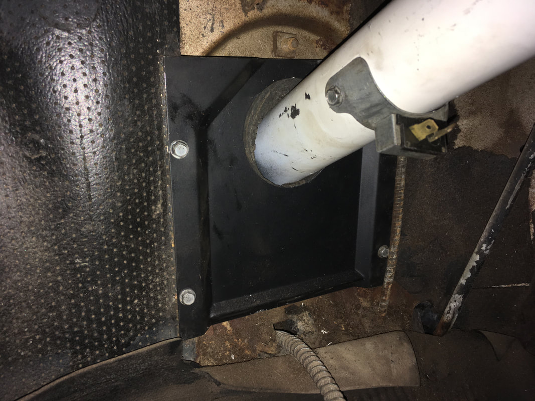
Position the firewall seal and attach the plate to the firewall. Try not to scratch the paint like I did.
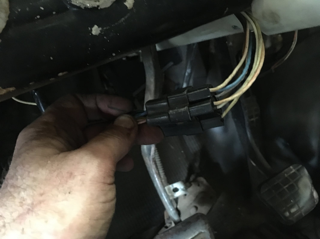
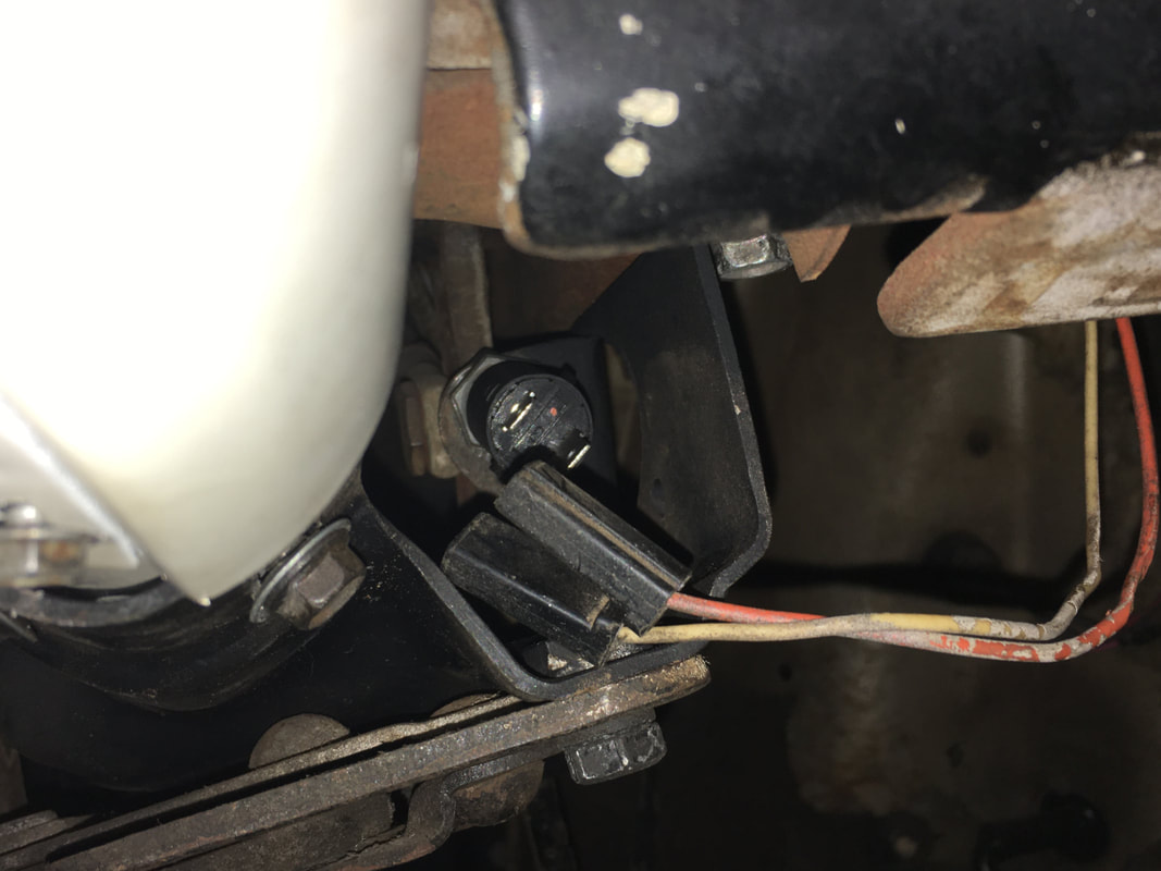
Reconnect the park brake handle to the column support bracket. Reconnect the 2 wires to the brake light switch.
|
|
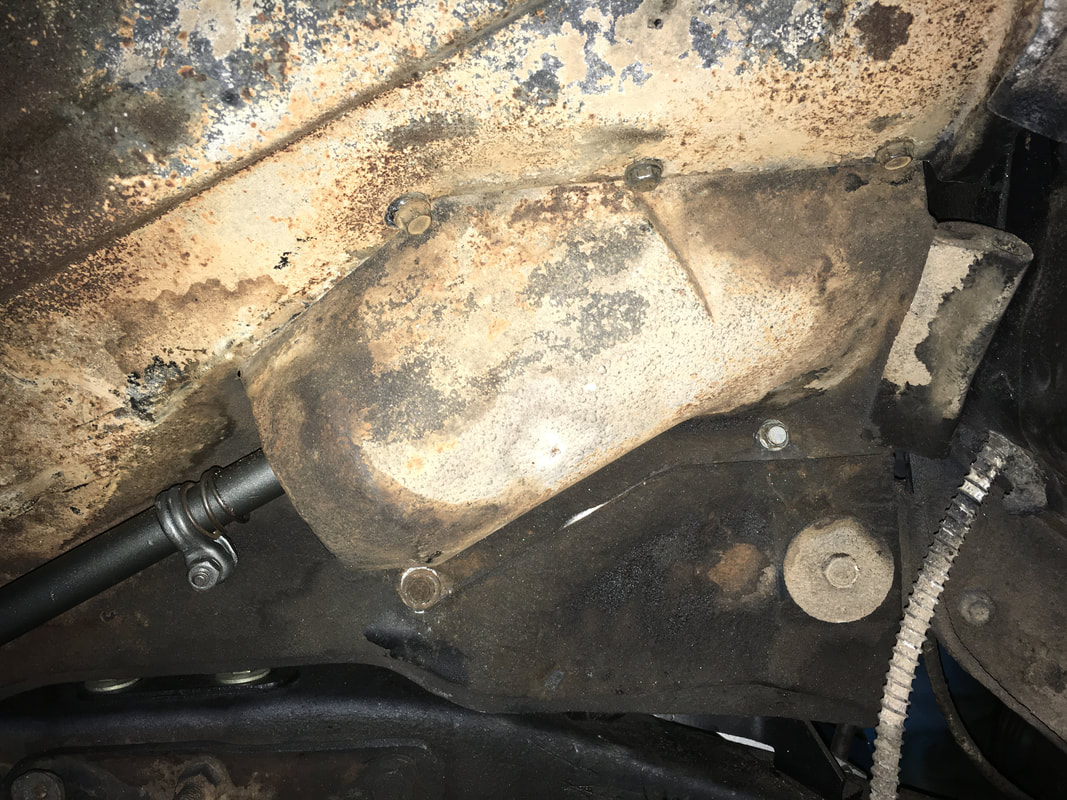
Replace the inner fender steering shaft cover.
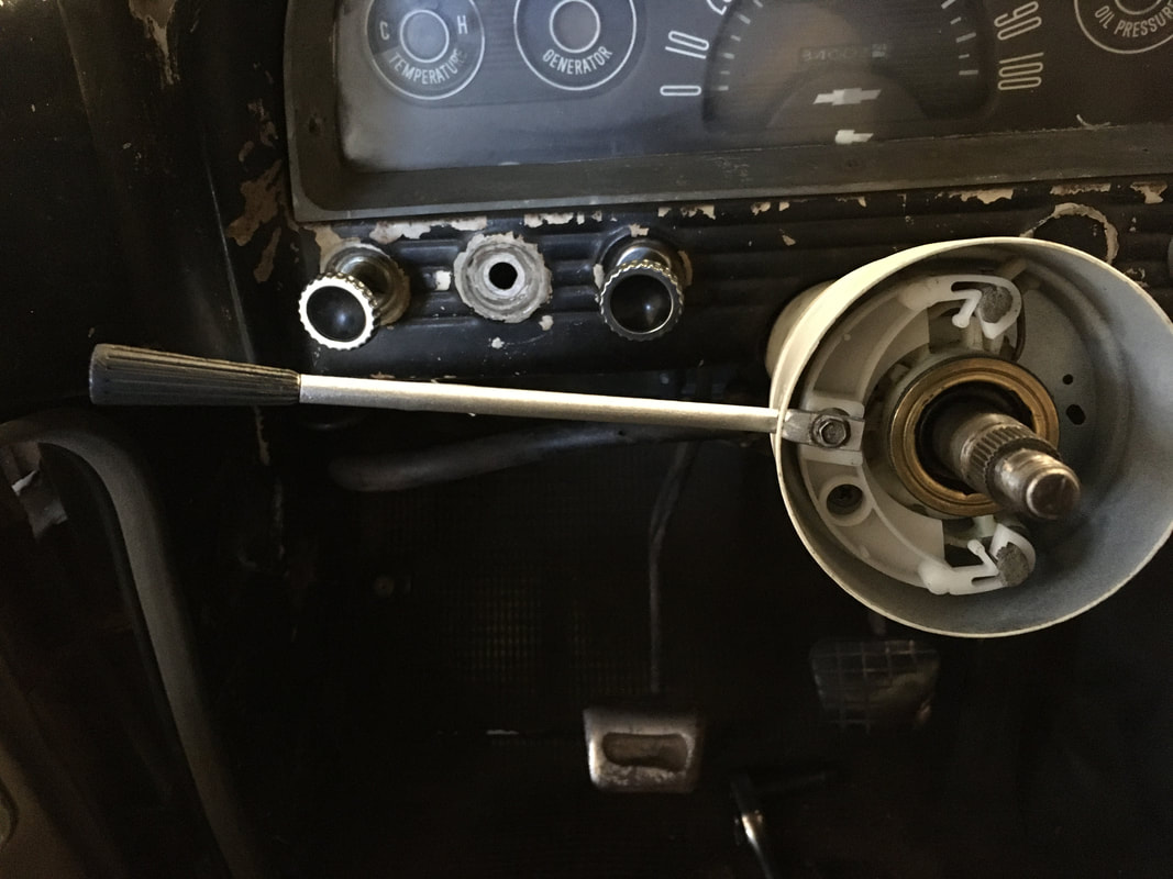
Replace the turn signal arm. Now is a good time to test the turn signals and horn. Turn the key to the ON position and make sure the turn signals and brake lights work properly. The horn should blow if you connect the brass ring to the column shaft with a jumper wire.
If the horn doesn't sound, then either the steering shaft is not properly grounded or there is a bad connection along the wire that connects the brass ring to the horn relay in the engine bay.
If the horn doesn't sound, then either the steering shaft is not properly grounded or there is a bad connection along the wire that connects the brass ring to the horn relay in the engine bay.
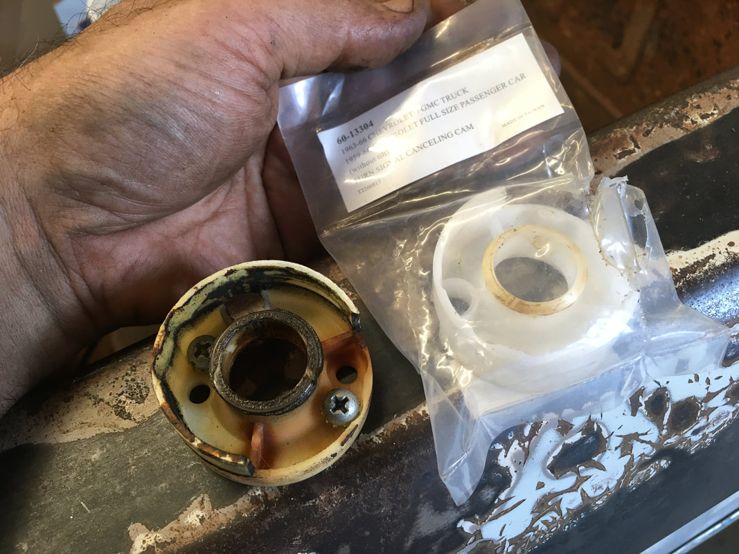
If your steering wheel needs a new turn signal cancelling cam, now is the time to replace it.
|
|
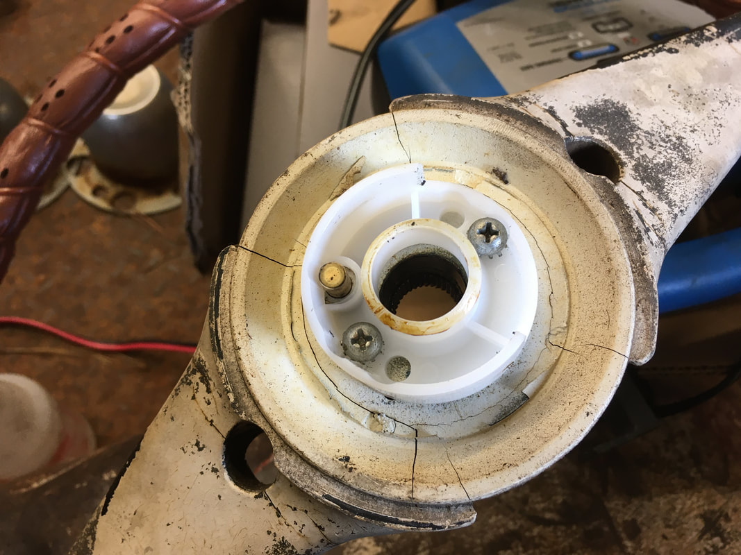
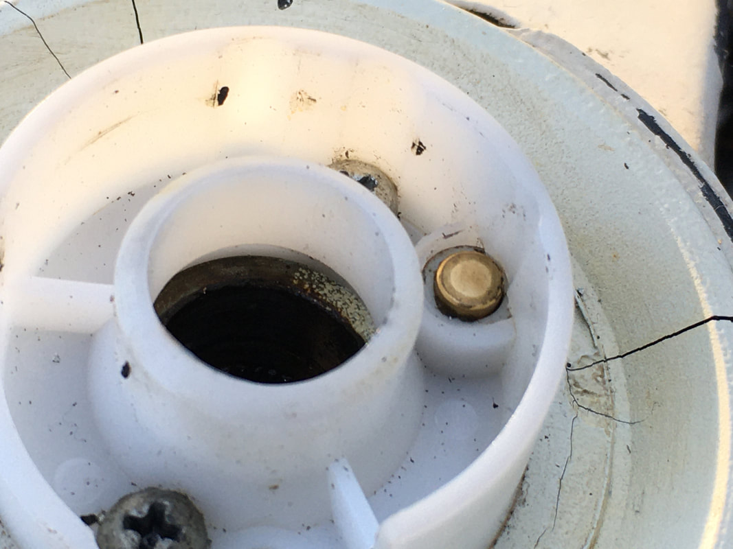
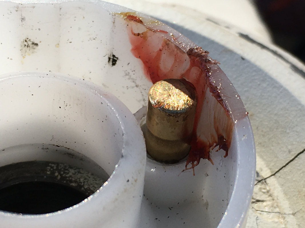
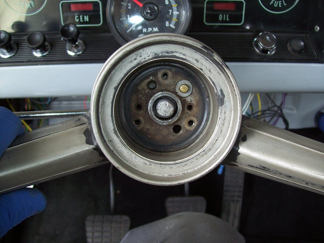
Push the brass plunger down to make sure it moves freely and springs back. Add a little grease or trim the plastic if necessary so it moves freely without binding. The center of this white plastic piece fits INSIDE the brass ring and sits immediately above the column upper bearing to help keep the bearing in place.
|
|
If your steering wheel has a HORN RING - follow these directions.
If your steering wheel has a horn button, please refer to the photos at the end of this DIY for details.
If your steering wheel has a horn button, please refer to the photos at the end of this DIY for details.
Add a little grease to the steering shaft splines. Line up the hash mark on the steering wheel with the mark on the steering shaft. Tap the steering wheel into place with your hands.
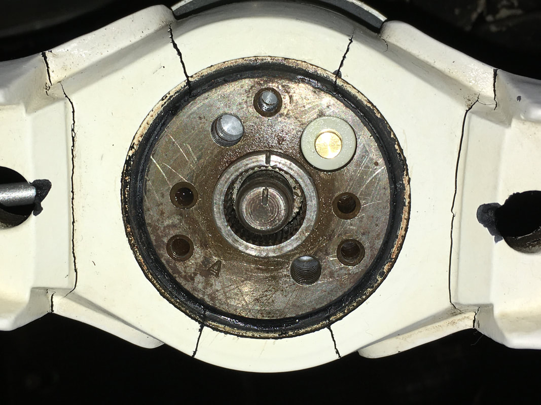
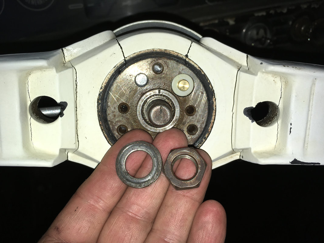
Replace the washer and nut. The shaft splines should fully engage with the steering wheel hub splines.
Use a jumper wire to connect the brass button to the steering wheel hub or steering shaft. The horn should sound. If the horn doesn't blow, then the steering hub brass button may not be making contact with the brass ring. You'll need to solve this problem before going further.
Use a jumper wire to connect the brass button to the steering wheel hub or steering shaft. The horn should sound. If the horn doesn't blow, then the steering hub brass button may not be making contact with the brass ring. You'll need to solve this problem before going further.
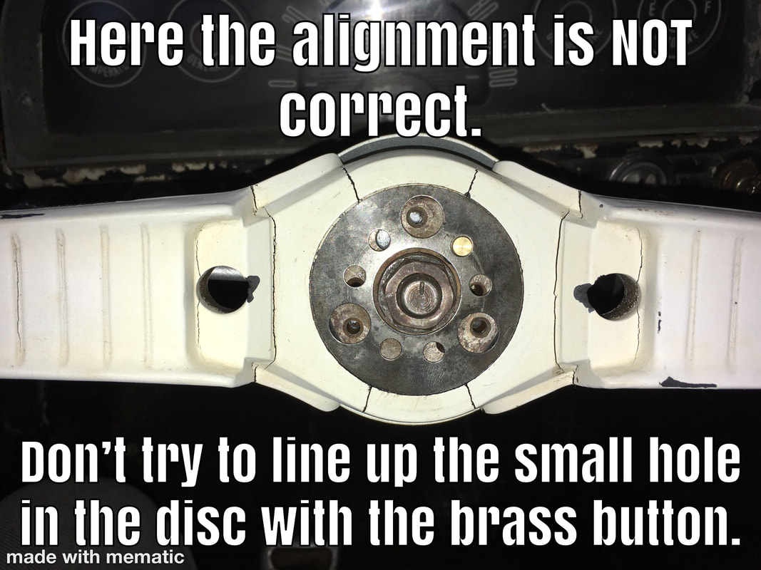
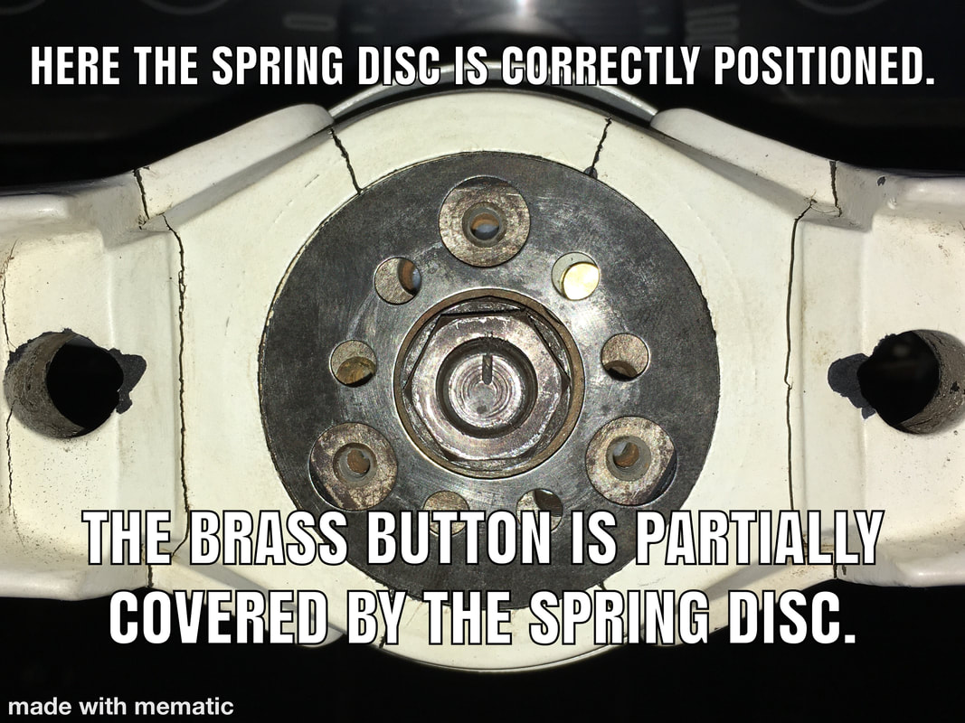
The spring disc goes on next. The small hole in the spring disc SEEMS like it should line up with the brass button, but that is NOT the proper position. Instead, the small hole should PARTIALLY cover the brass button. The 3 larger holes must be perfectly centered over the 3 screw holes.
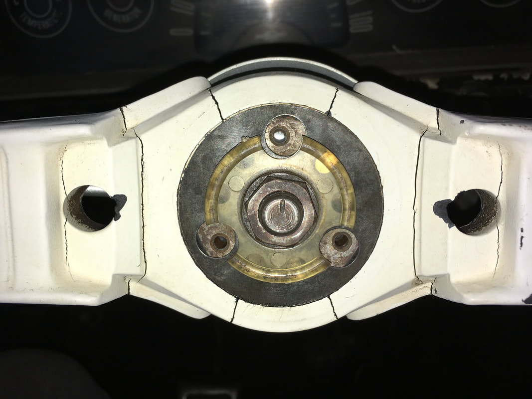
The plastic spacer goes on next (if you have a horn ring). The pic below shows the metal spring disc is STILL NOT correctly positioned, so an adjustment is needed. The plastic spacer is properly positioned.
The horn ring with the plastic insulator goes on next. The plastic sleeves that go through the horn ring insulate the 3 screws. These plastic sleeves must pass THROUGH the 3 large holes in the metal spring disc, and MUST NOT pinch the metal spring disc against the steering wheel hub.
Replace the 3 screws and test the horn.
When you blow the horn, here is what happens. Pressing the horn ring will cause the metal spring disc to touch the steering wheel hub which is grounded to the steering shaft. Since the metal spring disc is already in contact with the brass button in the steering wheel hub, the circuit to ground is completed to the brass ring. The brass ring is connected to the horn relay, so whenever the brass ring is connected to ground it will trip the horn relay and cause the horn to sound.
When you blow the horn, here is what happens. Pressing the horn ring will cause the metal spring disc to touch the steering wheel hub which is grounded to the steering shaft. Since the metal spring disc is already in contact with the brass button in the steering wheel hub, the circuit to ground is completed to the brass ring. The brass ring is connected to the horn relay, so whenever the brass ring is connected to ground it will trip the horn relay and cause the horn to sound.
Reconnect the center section of the steering wheel (horn ring version). My horn ring is broken but I have a replacement horn ring that I'll install when I restore my steering wheel. Test the horn again.
Loosen the 2 bolts in the slotted holes and slide the column main tube towards the steering wheel until it stops. Tighten the bolts. This adjustment properly positions the turn signal collar up against the steering wheel. The steering wheel should not rub the turn signal collar.
Replace the column support bracket and strap on the firewall inside the engine bay.
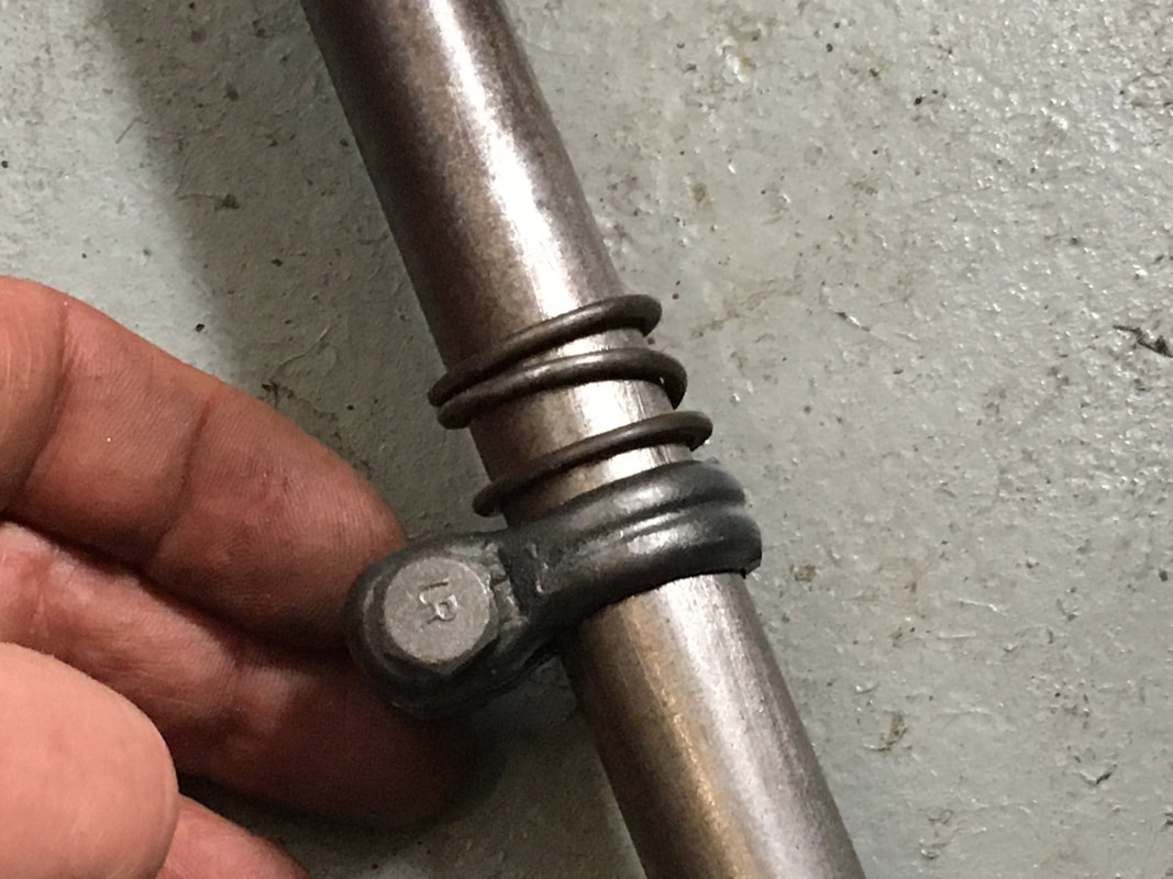
Slide the spring up against the lower column bearing with slight tension and tighten the clamp. The spring should only LIGHTLY press on the lower bearing. Reconnect the transmission shifter linkages to the lower column shift arms.
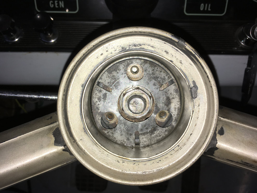
If your steering wheel has a HORN BOTTON - follow these directions.
If your steering wheel has a horn ring, please refer to the photos earlier in this DIY for details.
If your steering wheel has a horn ring, please refer to the photos earlier in this DIY for details.
Add a little grease to the steering shaft splines. Line up the hash mark on the steering wheel with the mark on the steering shaft. Tap the steering wheel into place with your hands.
Replace the washer and tighten the nut onto the steering shaft.
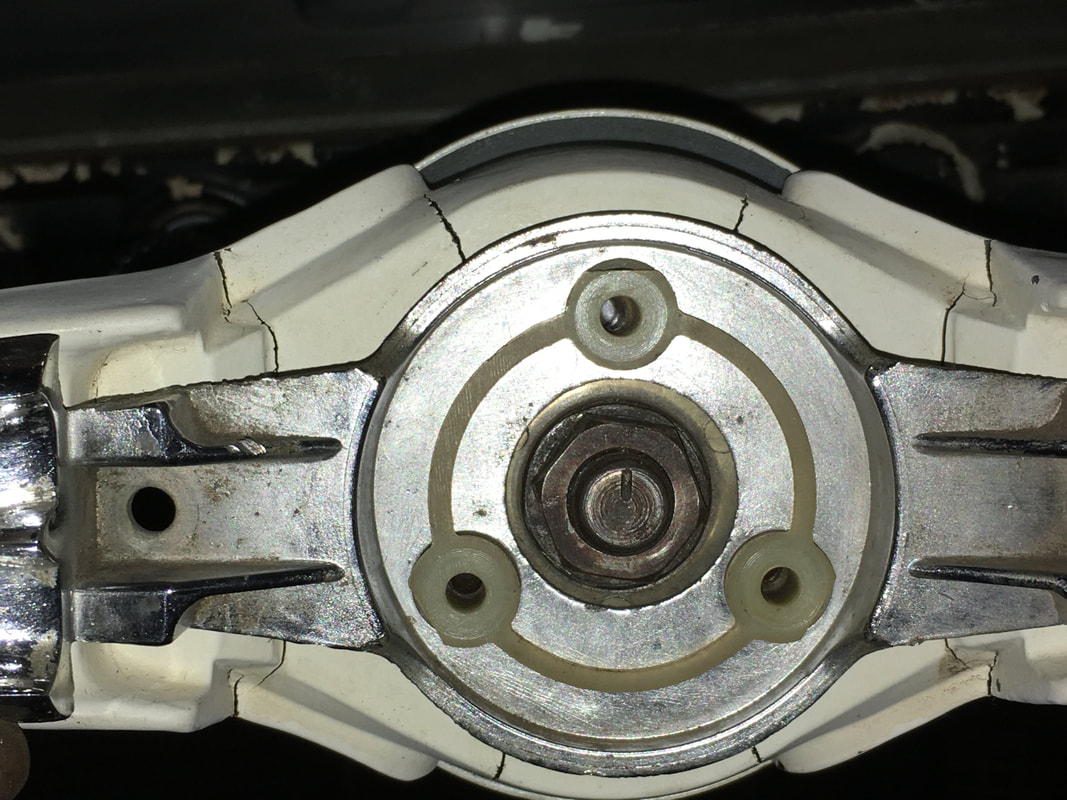
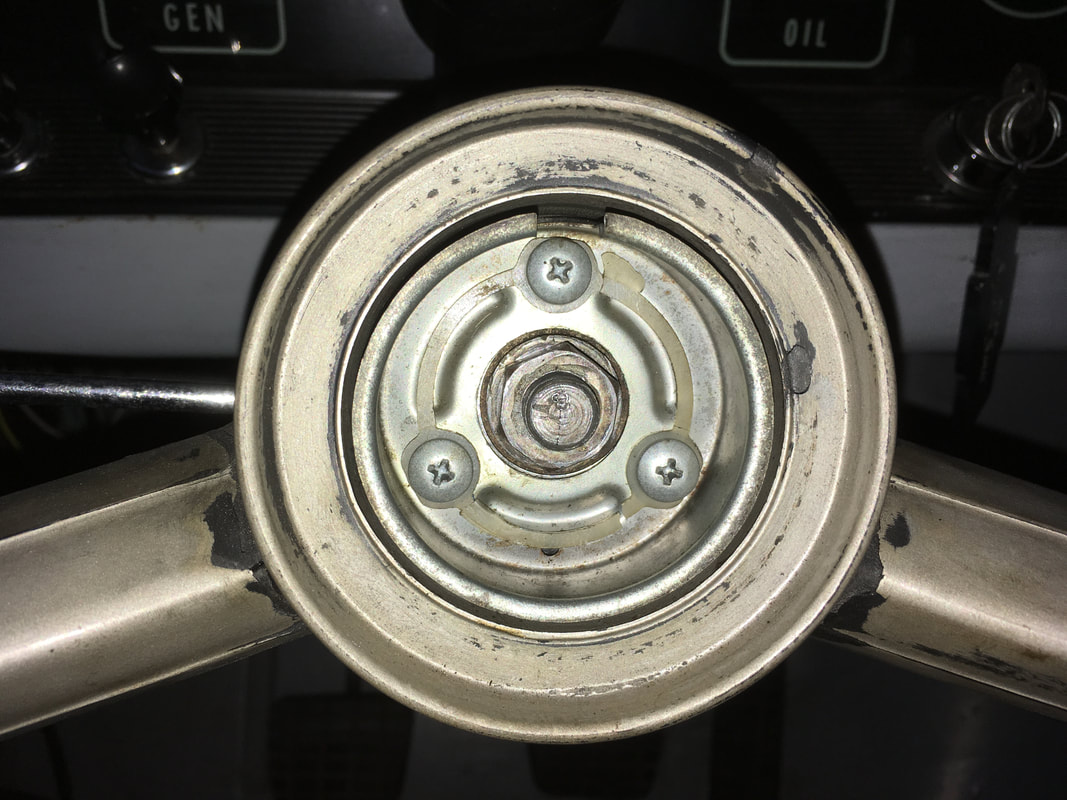
Replace the spring disc and line it up with the 3 screw holes.
Replace the spring disc and line it up with the 3 screw holes.
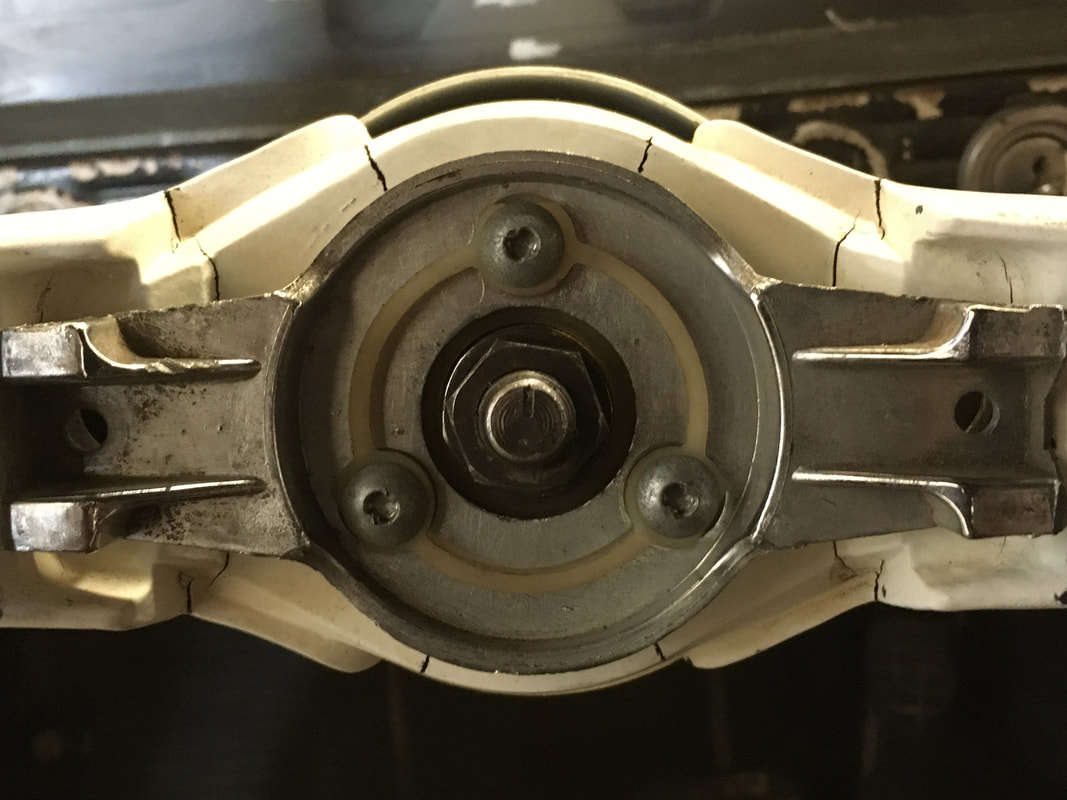
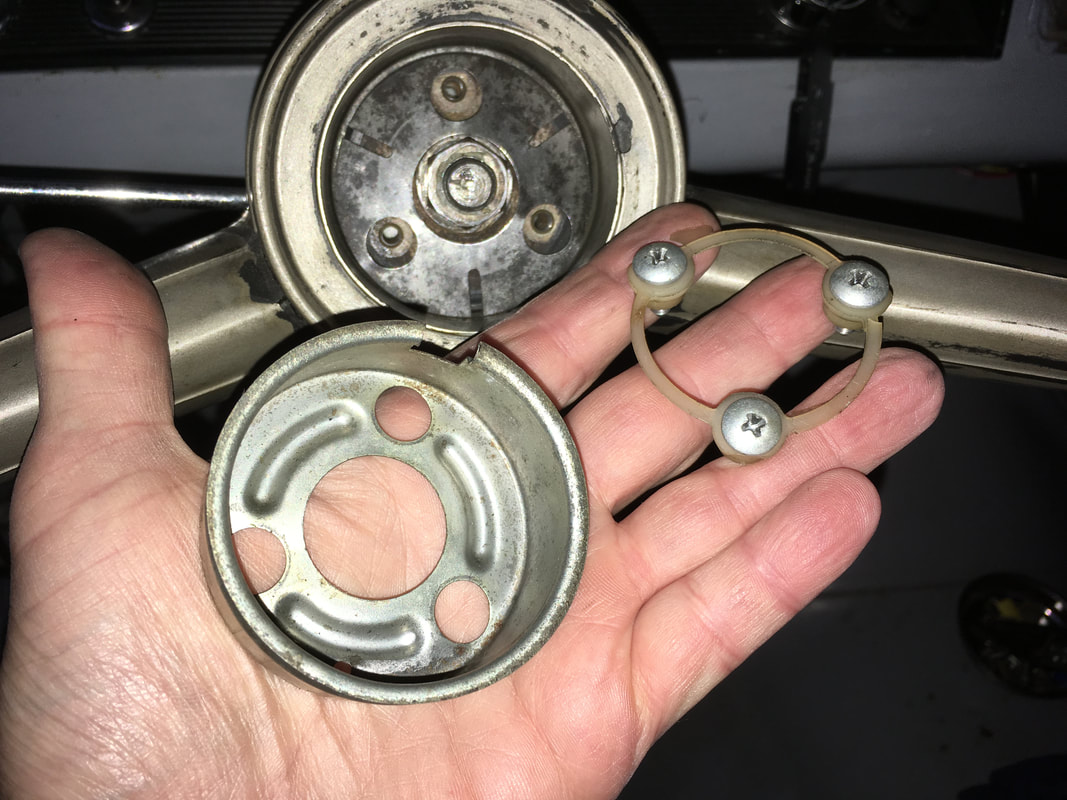
The horn cup with the plastic insulator goes on next. The notch in the horn cup is for the horn button and should be at the 12 o'clock position on the steering wheel. The plastic sleeves that go through the horn cup insulate the 3 screws. These plastic sleeves must pass THROUGH the 3 large holes in the metal spring disc, and MUST NOT pinch the spring disc against the steering wheel hub.
|
|
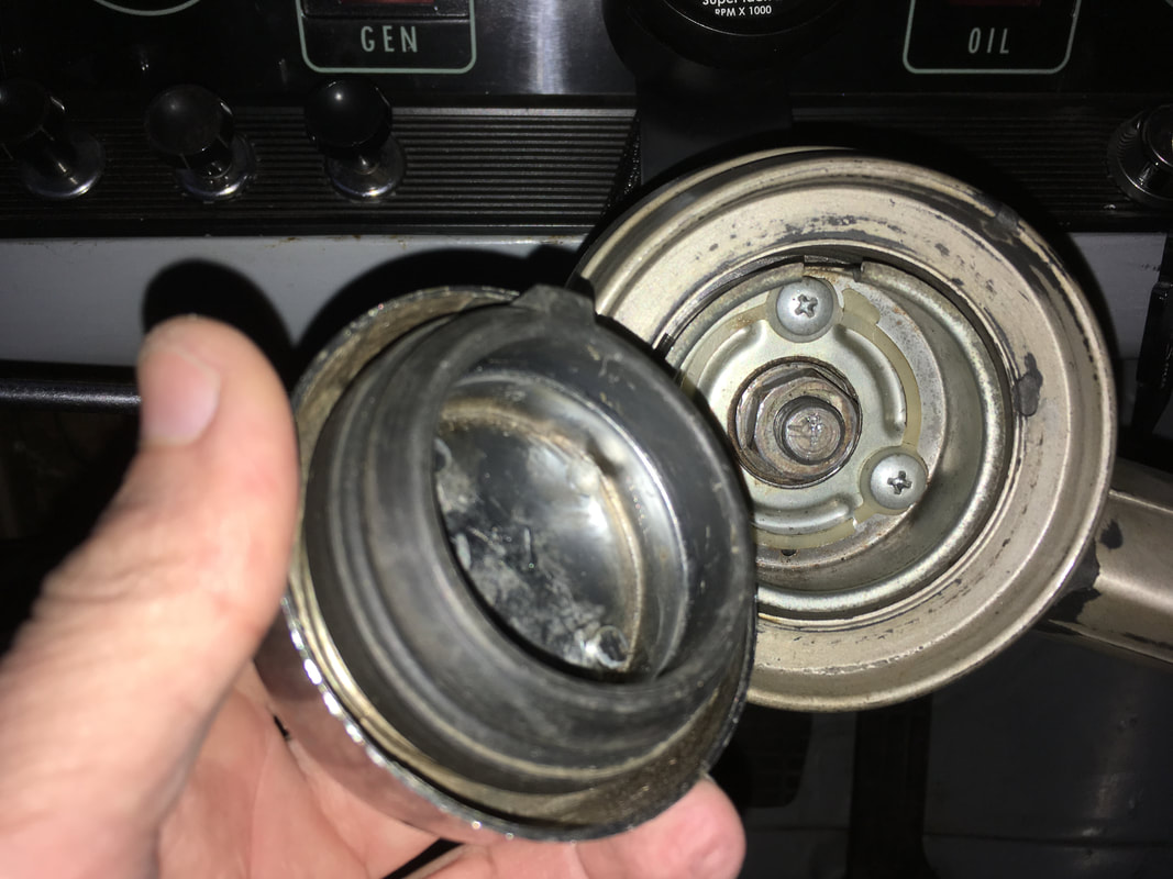
Line up the horn button with the notch in the horn cup and press the button into place. Test the horn.
When you blow the horn, here is what happens. Pressing the horn button will cause the metal spring disc to touch the steering wheel hub which is grounded to the steering shaft. Since the metal spring disc is already in contact with the brass button in the steering wheel hub, the circuit to ground is completed to the brass ring. The brass ring is connected to the horn relay, so whenever the brass ring is connected to ground it will trip the horn relay and cause the horn to sound.
When you blow the horn, here is what happens. Pressing the horn button will cause the metal spring disc to touch the steering wheel hub which is grounded to the steering shaft. Since the metal spring disc is already in contact with the brass button in the steering wheel hub, the circuit to ground is completed to the brass ring. The brass ring is connected to the horn relay, so whenever the brass ring is connected to ground it will trip the horn relay and cause the horn to sound.
|
|