1963 Chevy C10 Steering Column Disassembly
You will need to carefully inspect each piece as you disassemble the steering column.
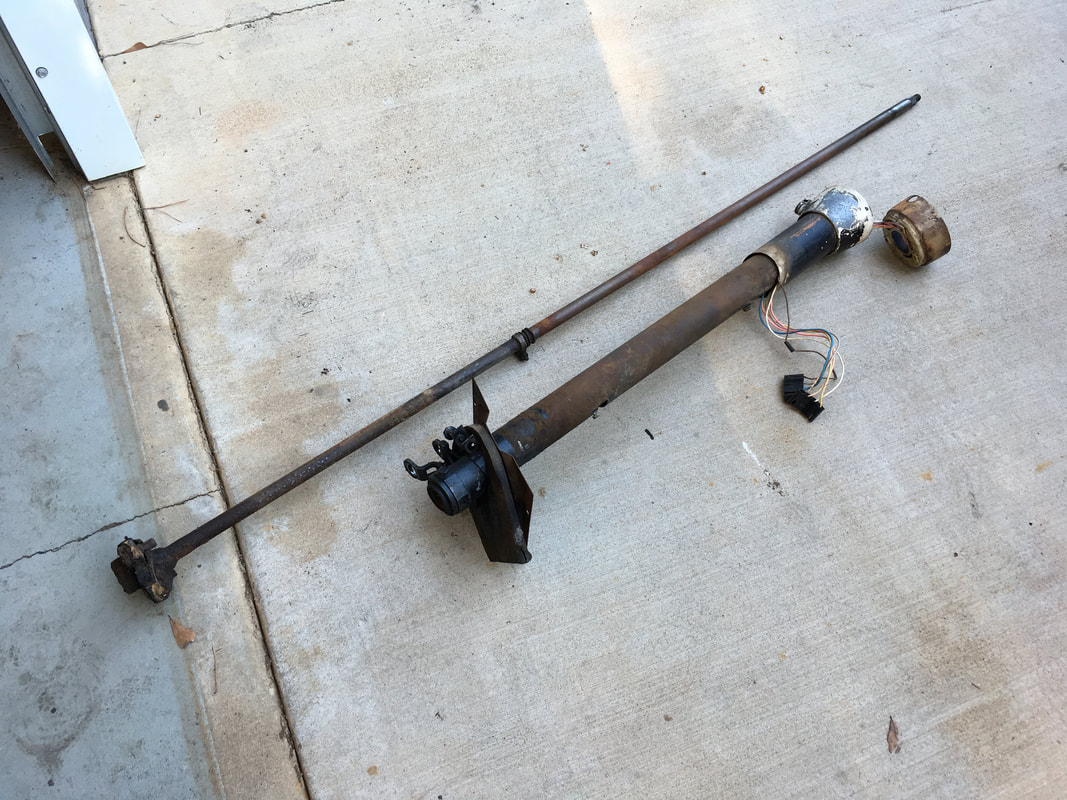
1. INSPECT THE SHAFT
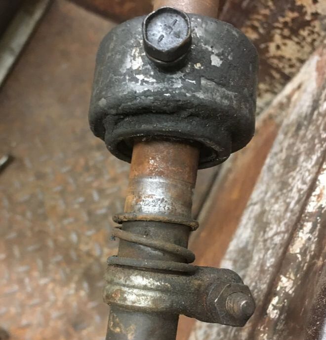
The long thin rod in the photo above is the steering shaft. It is sometimes referred to as "the mast".
**IMPORTANT** - If the shaft has any damage it should be replaced or professionally repaired (if possible). A common area of damage is at the location of the lower column bearing. See photos below.
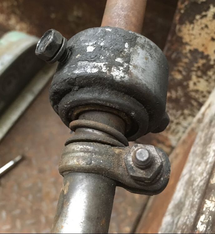
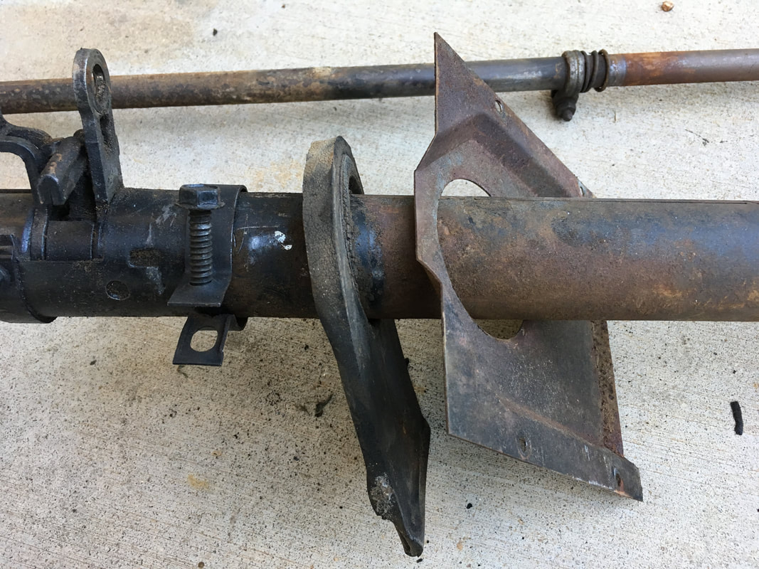
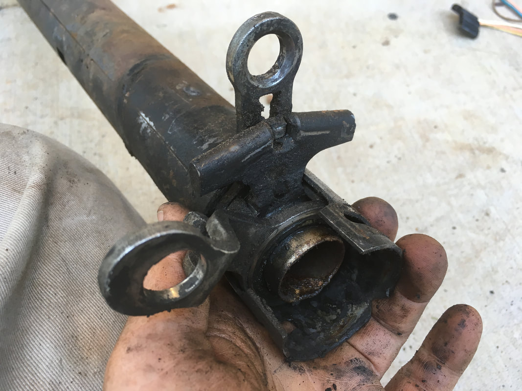
In the middle of the shaft is a clamp and spring that supports the lower bearing. Examine the entire shaft for any scoring, gouging or wear, especially at the lower bearing location. If the lower bearing fails it can cut deep grooves into the shaft which weakens the shaft and makes it UNSAFE. The shaft pictured below shows normal wear and no damage or excessive wear.
**IMPORTANT** - If the shaft has any damage it should be replaced or professionally repaired (if possible). A common area of damage is at the location of the lower column bearing. See photos below.
In the middle of the shaft is a clamp and spring that supports the lower bearing. Examine the entire shaft for any scoring, gouging or wear, especially at the lower bearing location. If the lower bearing fails it can cut deep grooves into the shaft which weakens the shaft and makes it UNSAFE. The shaft pictured below shows normal wear and no damage or excessive wear.
|
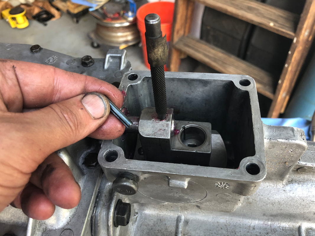
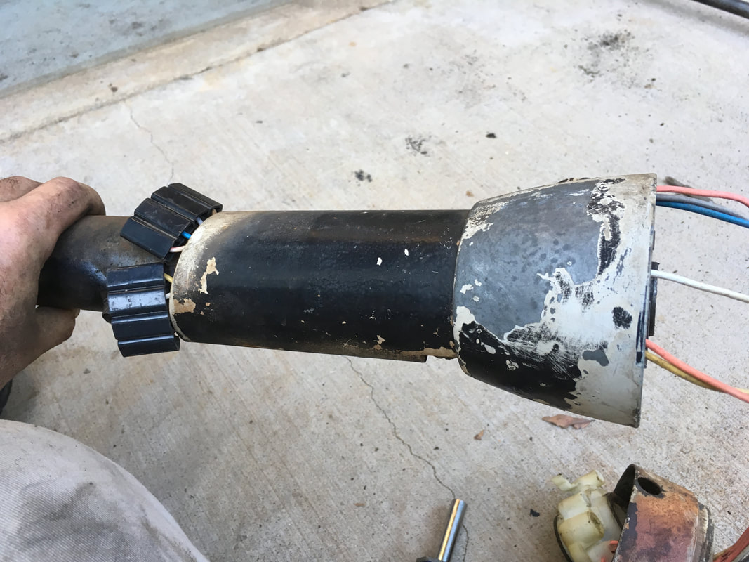
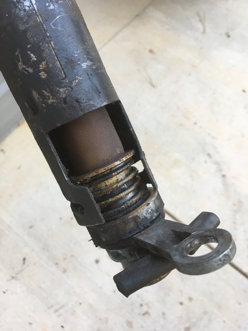
In this picture, I placed the lower bearing back onto the shaft to show where it normally lives. The rest of the column has been removed for clarity.
|
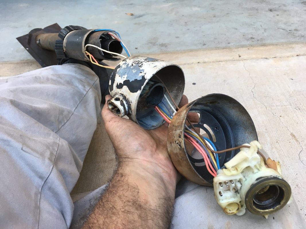
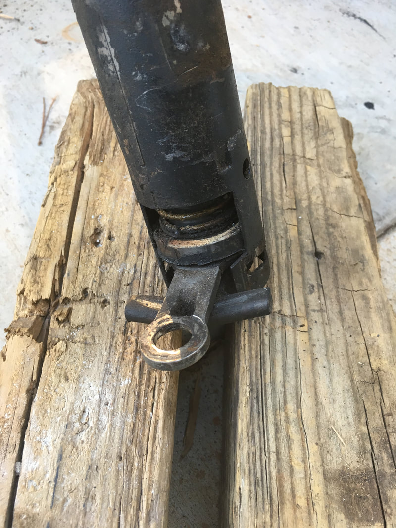
In this picture, I moved the bearing up and away from the spring. The area just above the spring is without damage. Normal wear is present. Any damage would need professional repair.
|
If the shaft is in good shape, then rebuilding the steering column should be worthwhile. If the shaft is damaged, find another shaft before spending time or money on a rebuild.
2. DISASSEMBLY
Remove the 3 screws that hold the turn signal mechanism to the upper collar. Use your fingers to pivot the turn signal cam so you can access the top and bottom screws.
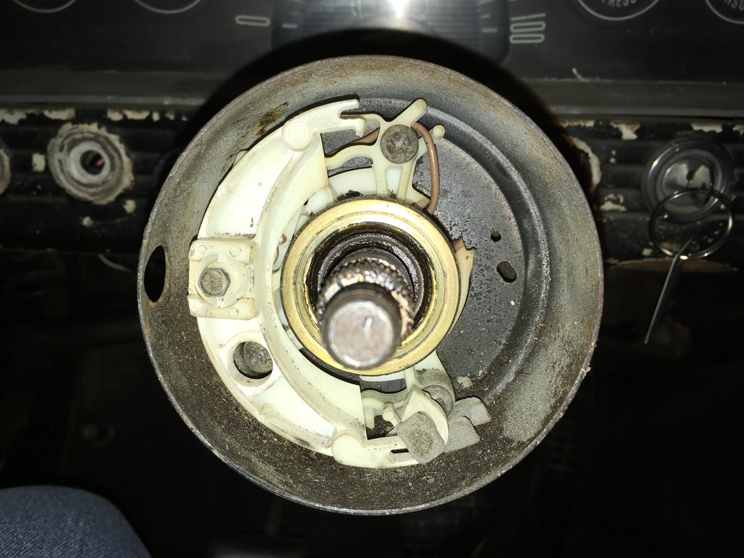
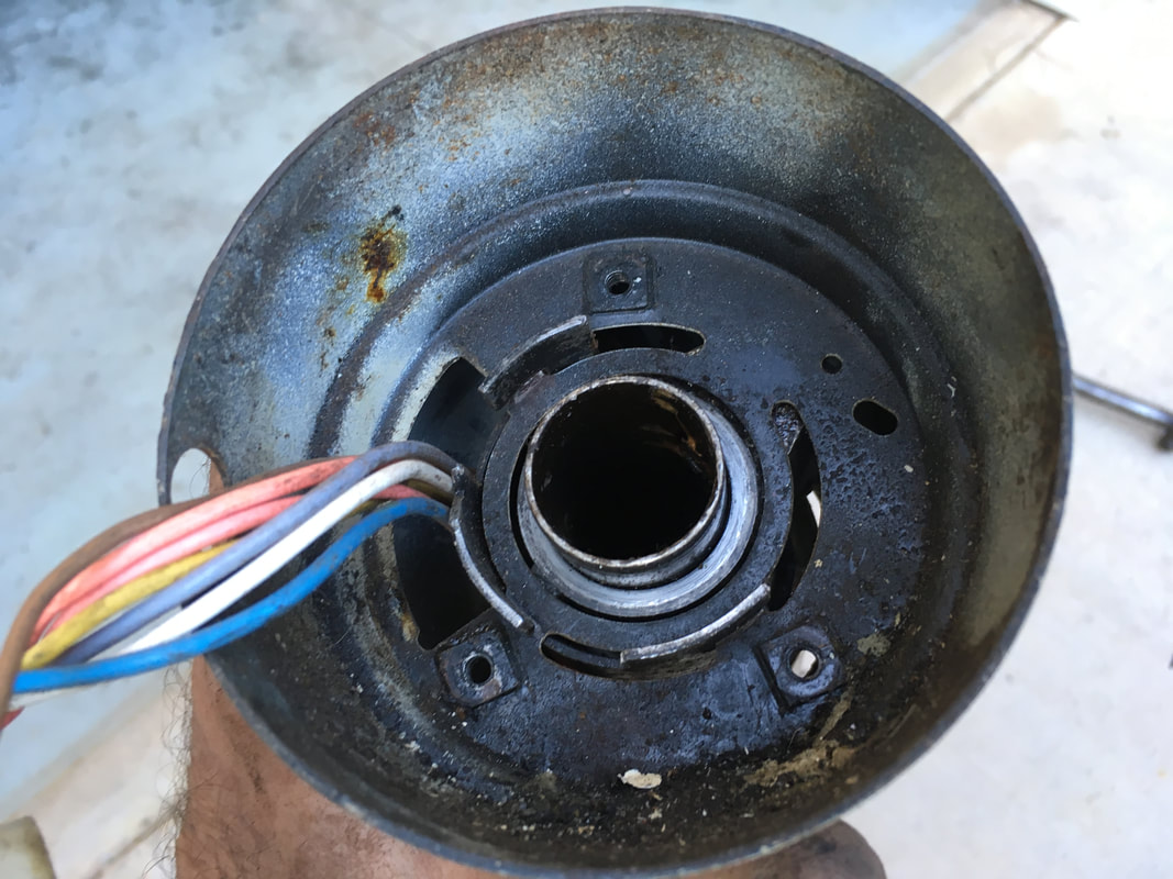
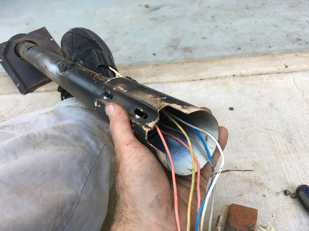
Work the wires up through the side of the column. The slack will allow you to pull the turn signal mechanism out of the collar. This picture shows the large brass horn contact ring. The brown wire is clipped to a tab on the horn contact ring. The steering shaft fits through the center of the upper column bearing. The upper bearing sits inside the plastic and around the shaft but should NOT contact the brass ring.
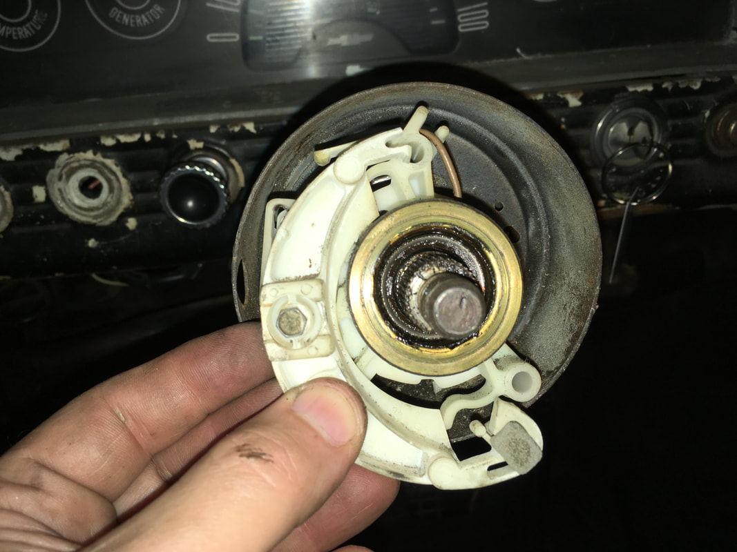
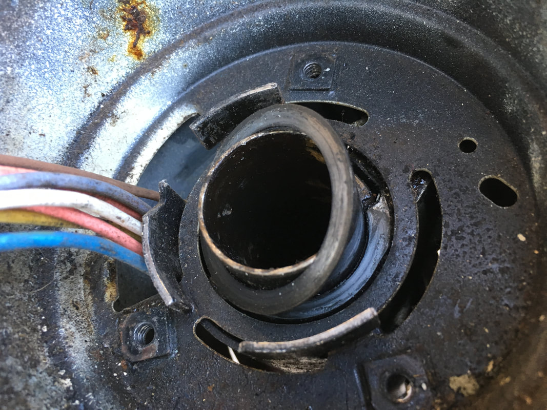
Resist the temptation to remove the screw that holds the turn signal cam in place. (You can see a broken piece of my turn signal cam laying inside the collar in this picture.)
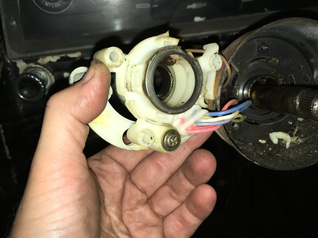
You will find a bushing at the top of the column (tilted up here for clarity).
Work the wires up through the short outer sleeve as pictured below. The turn signal mechanism and upper collar are now free to move away from the shifter collar.
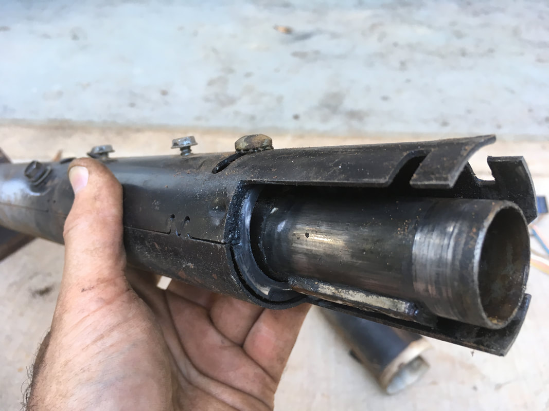
The shifter collar can now slide off of the shifter tube. Here you can see the inner shifter tube, the main column sleeve and a short outer sleeve that covers the wires.
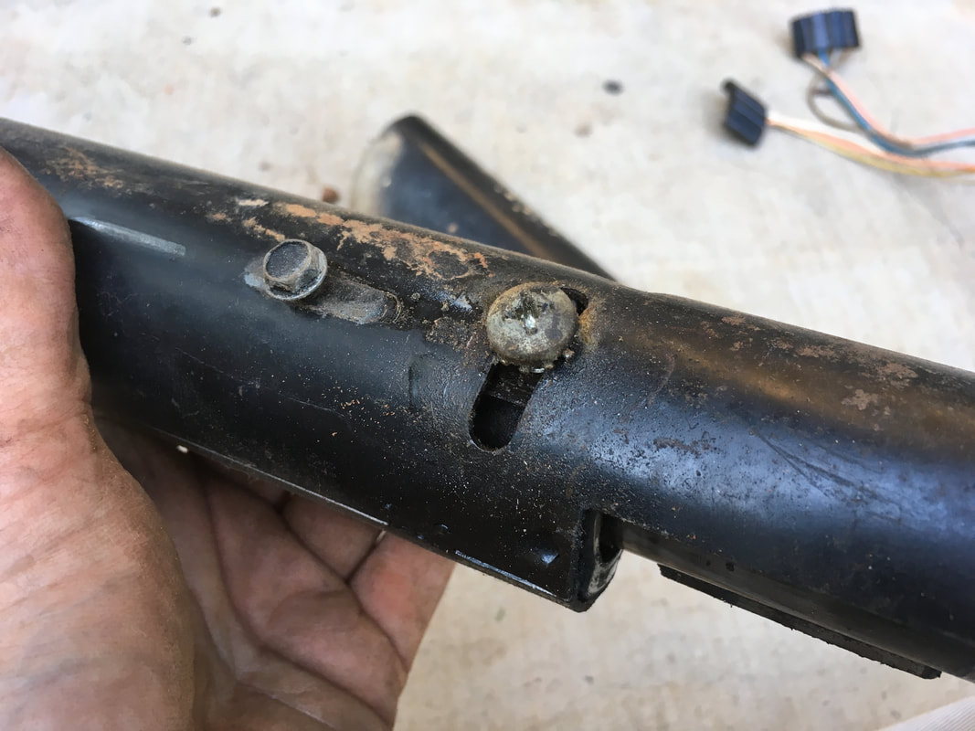
Remove the 2 screws that hold the short outer sleeve to the main sleeve. Slide the short sleeve and wires off the main sleeve.
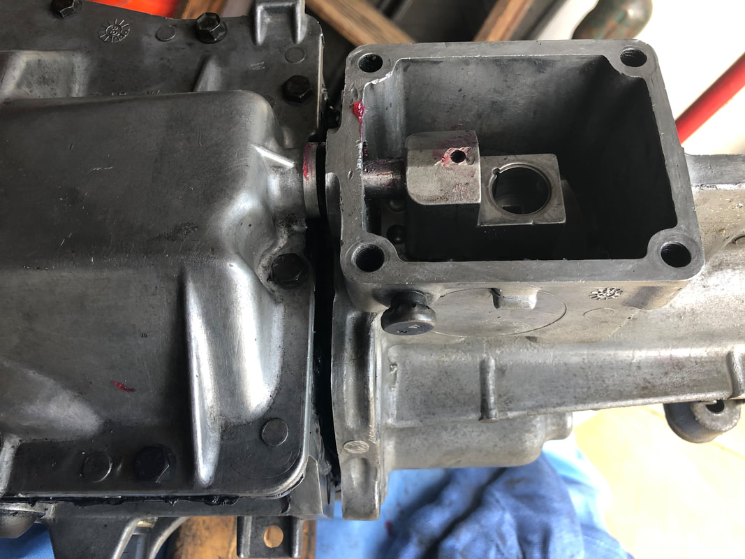
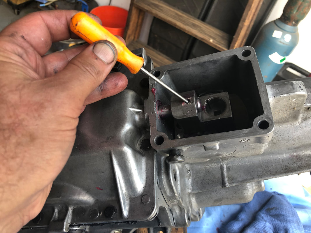
The large machine screw in the center of this picture holds an adjustment ring. Remove the screw and remove the ring.
|
|
Slide the firewall plate, rubber seal and firewall bracket strap off the column.
Two bolts hold the lower column bearing to the very bottom of the main column sleeve. The bolts go through two holes in a "C" shaped band that fits around the main sleeve.
Remove the bolts, band and bearing.
|
|
The lower shift arm can now be removed from the shifter tube.
|

|
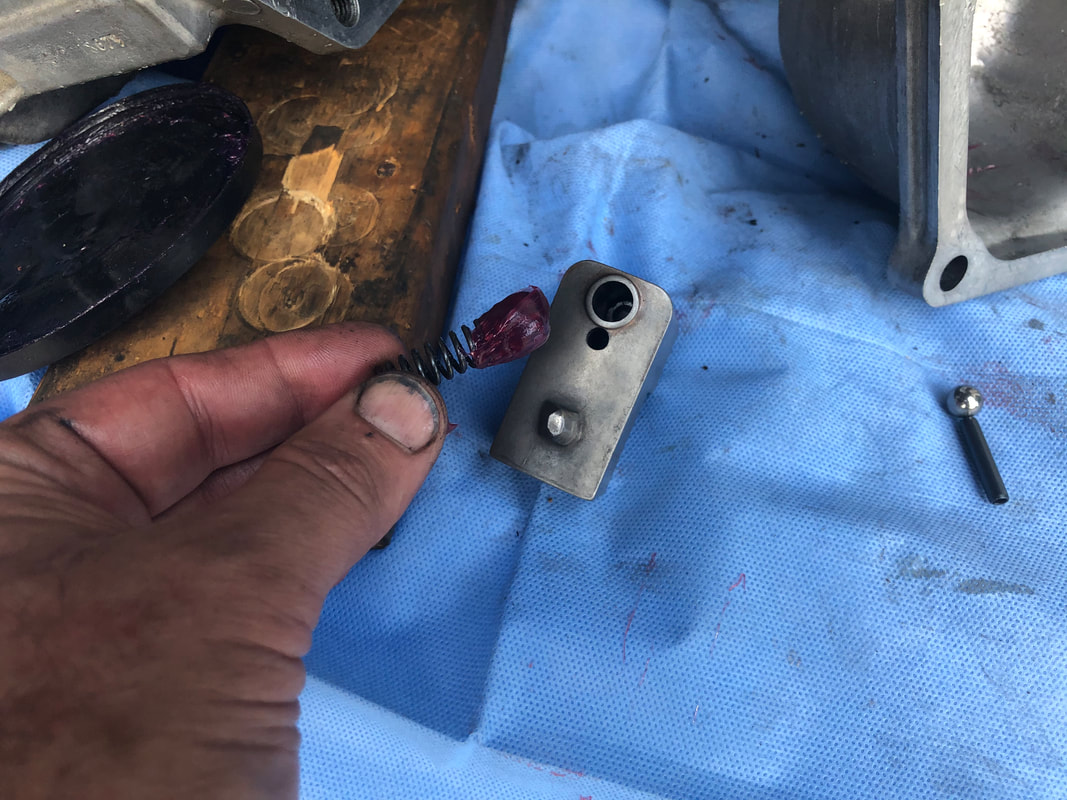
Remove the "C" shaped spacer that was above the lower shift arm. Now all that remains is the main sleeve, the shifter tube and the 2 pieces connected to the lower part of the shifter tube. At the top of the column, if you push down on the top of the shifter tube you will feel tension from a spring inside the column.
Rest the bottom of column on 2 blocks of wood. The blocks should be close enough to support the edges of the main column sleeve but far enough apart that the shifter tube can fit between them when the time comes.
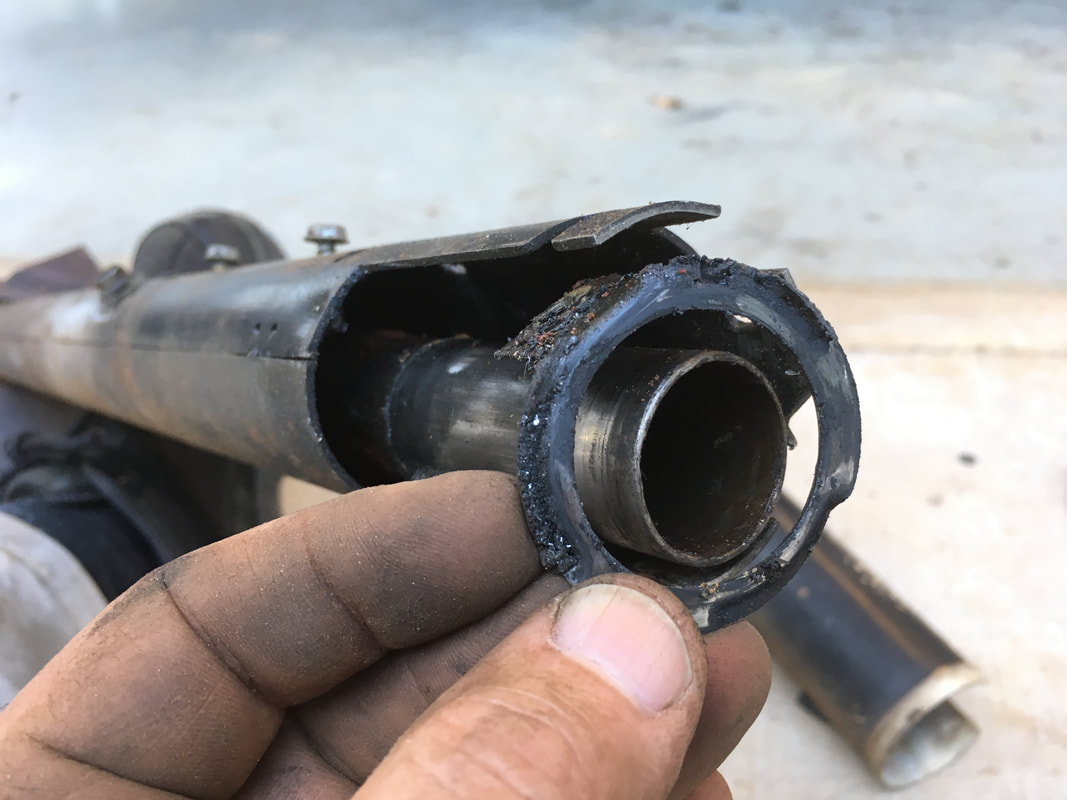
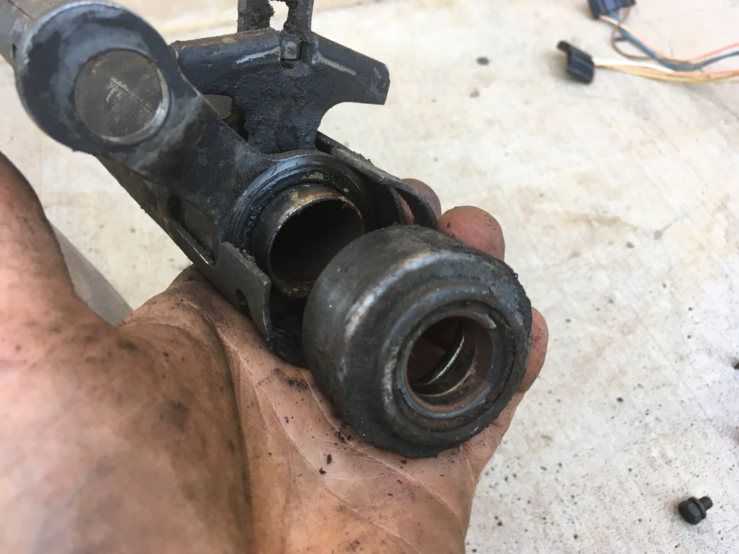
You will now drive the shifter tube downward inside the outer sleeve until it is free. To accomplish this, place a small block of wood on the top end of the shifter tube and press down until the spring is fully compressed. With the spring compressed, use a rubber mallet to firmly tap the block of wood you are holding. The force will gradually move the shifter tube down inside the main sleeve. These 2 photos show the shifter tube half way and then fully out. You can see the spring above the bushing that holds the shifter tube inside the main sleeve.
|
|
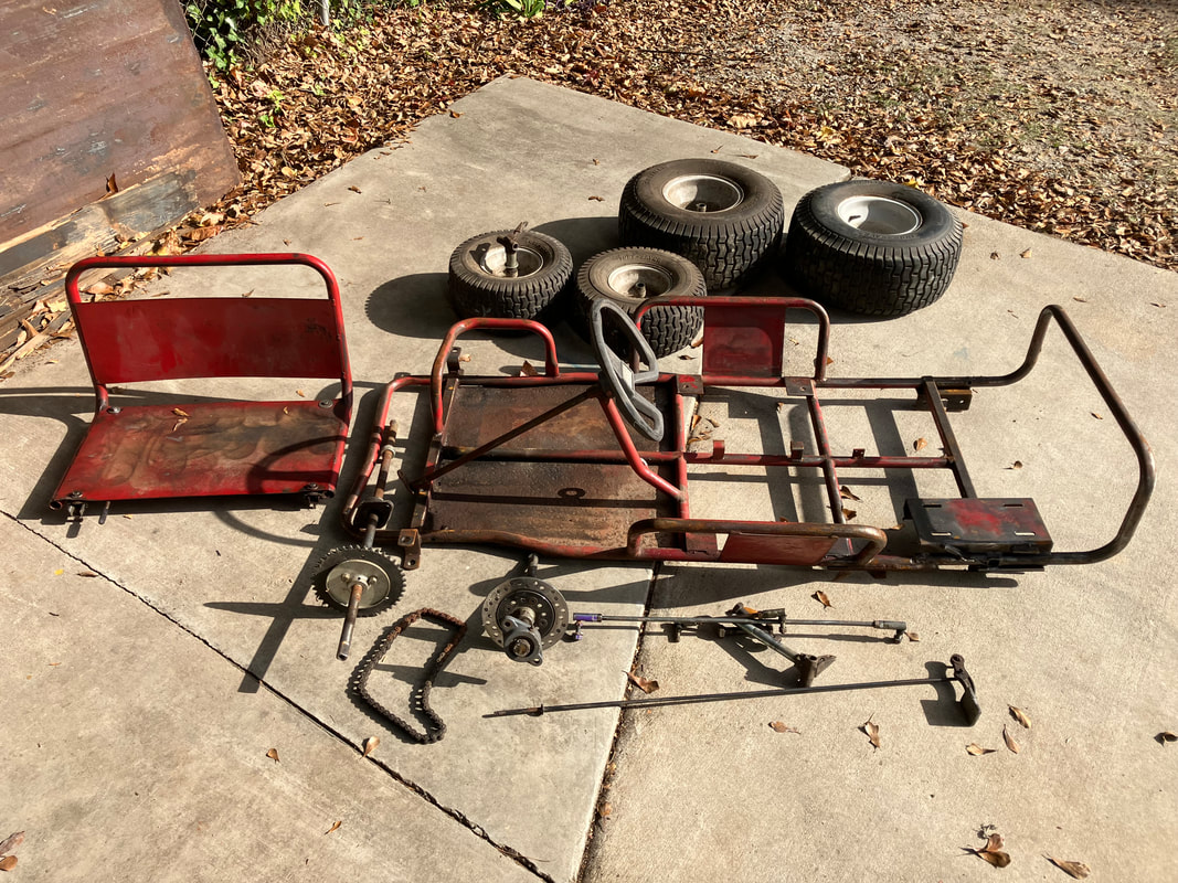
Remove the turn signal mechanism from the upper collars. You now have a pile of parts to clean, inspect and keep track of. Stay organized and keep everything together.