Today was the first time I used a propane torch to heat the metal prior to banging out a dent. I said "banging" because with no formal training, that's about what it amounts to. I just do my best. I've said it many times, "Yes, I'm doing it all myself. It's a truck, not a Ferrari."
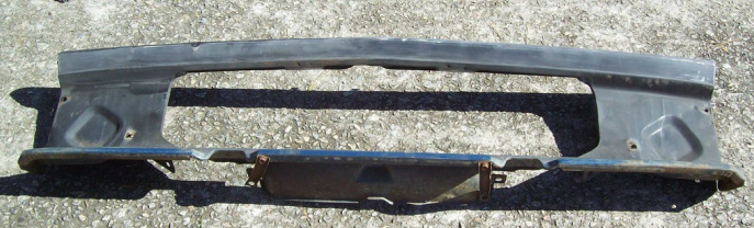
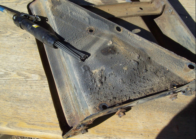
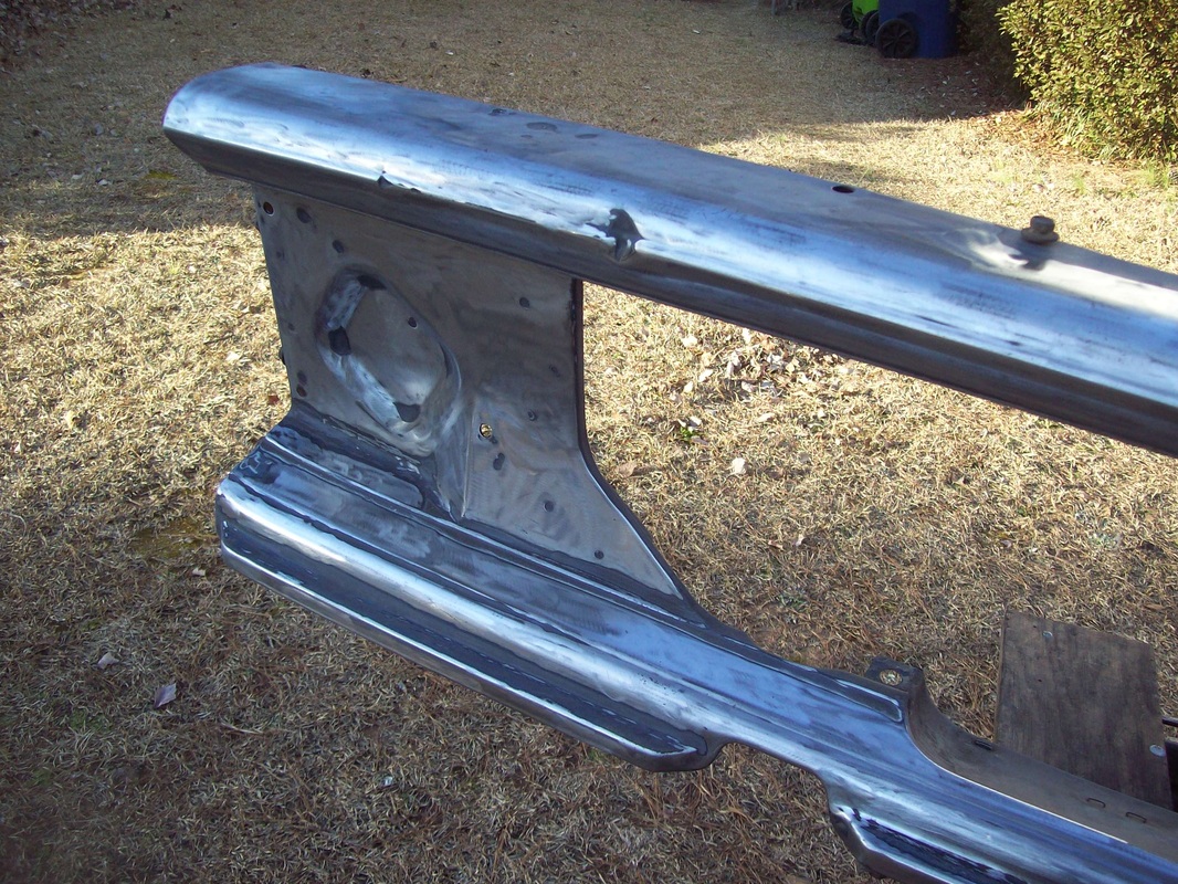
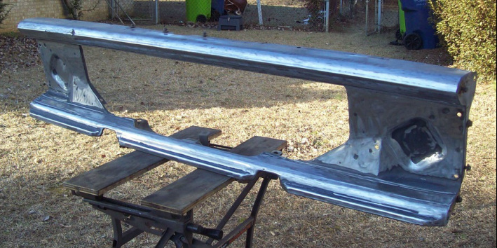
My grille support is in great shape but has a few small dents. Nothing too serious. Unfortunately, the dents are along the body lines, making the work more challenging. Here are a few Before, Half-way, and After pics. A skim of body filler and it will be good enough for me.
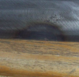
| Before 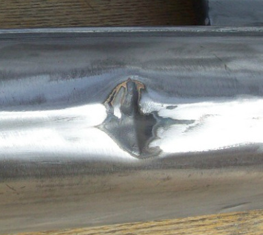
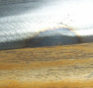
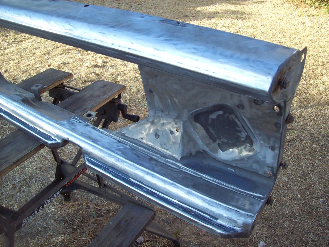
After 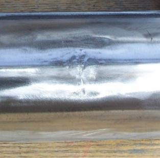
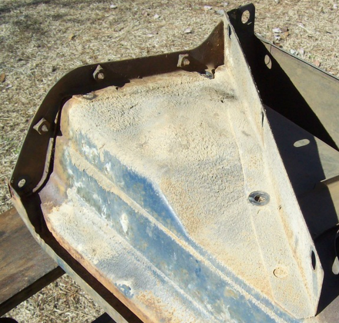
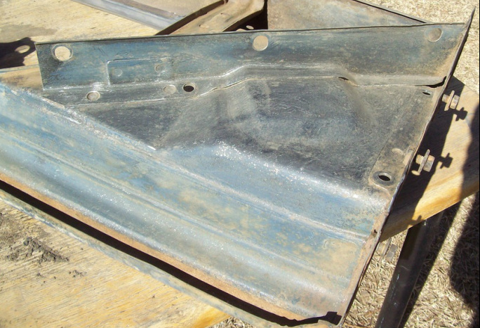
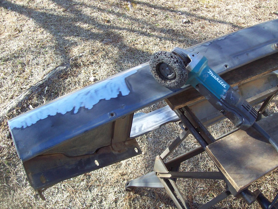
| Half-way 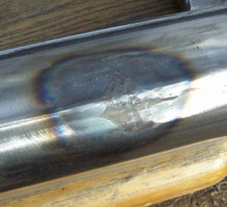
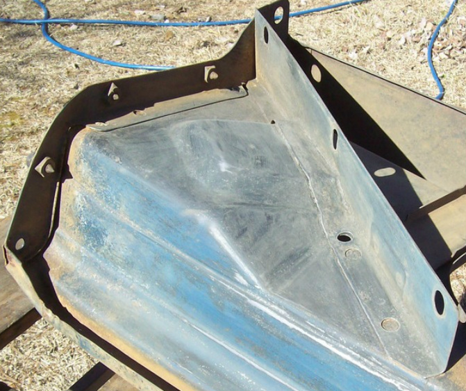
After 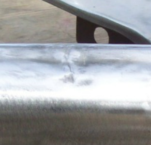
|
| Before 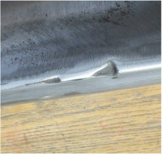
After | Half-way 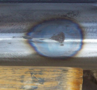
After |
| 
|

 RSS Feed